Method and system for remote monitoring and surveillance

a technology of applied in the field of methods and systems for remote monitoring and surveillance, can solve problems such as the danger of being robbed by the truck delivering cash

Inactive Publication Date: 2009-02-26
BANDRICH
View PDF4 Cites 168 Cited by
  • Summary
  • Abstract
  • Description
  • Claims
  • Application Information

AI Technical Summary

Problems solved by technology

During the cash delivery, the truck delivering cash is in danger of being robbed.

Method used


Image

  • Method and system for remote monitoring and surveillance
  • Method and system for remote monitoring and surveillance
  • Method and system for remote monitoring and surveillance

Examples


first embodiment

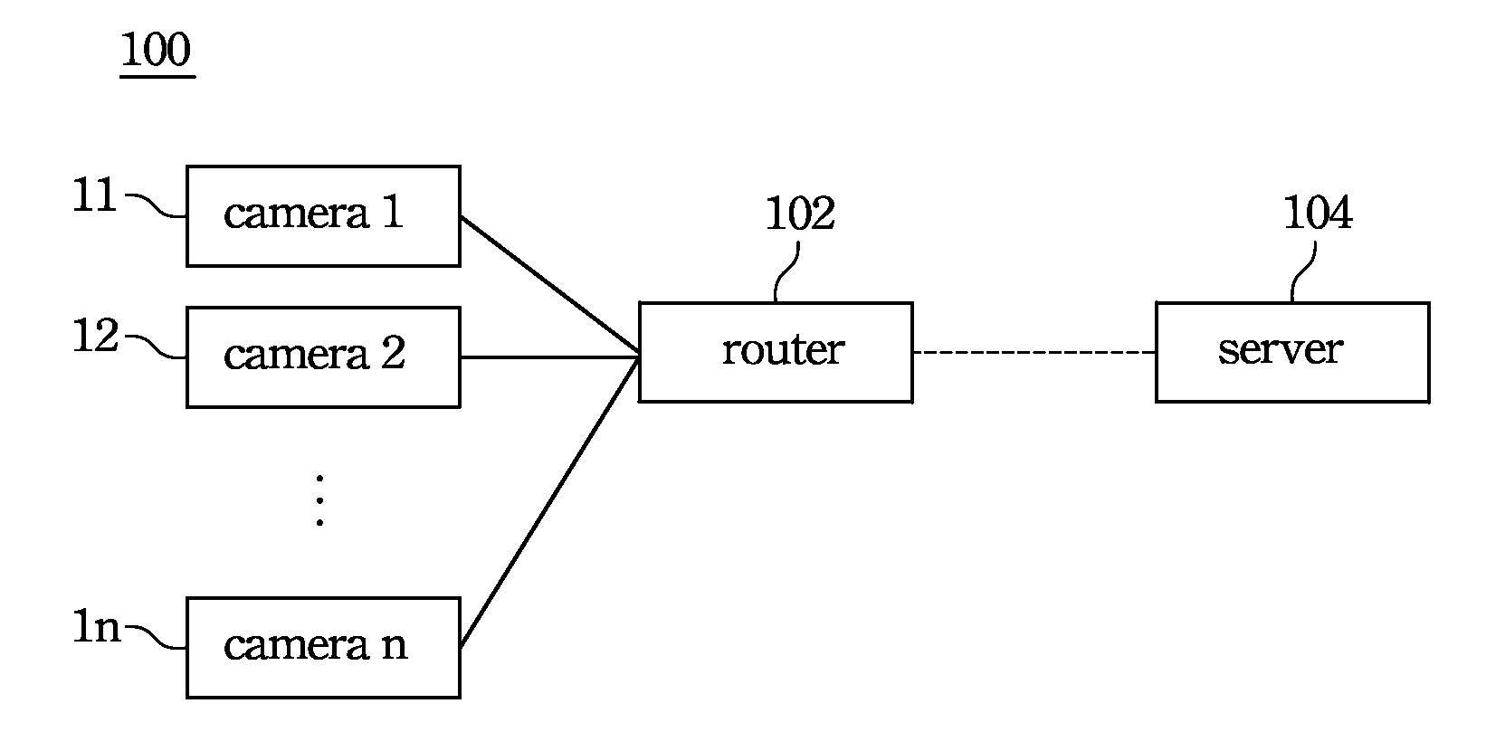
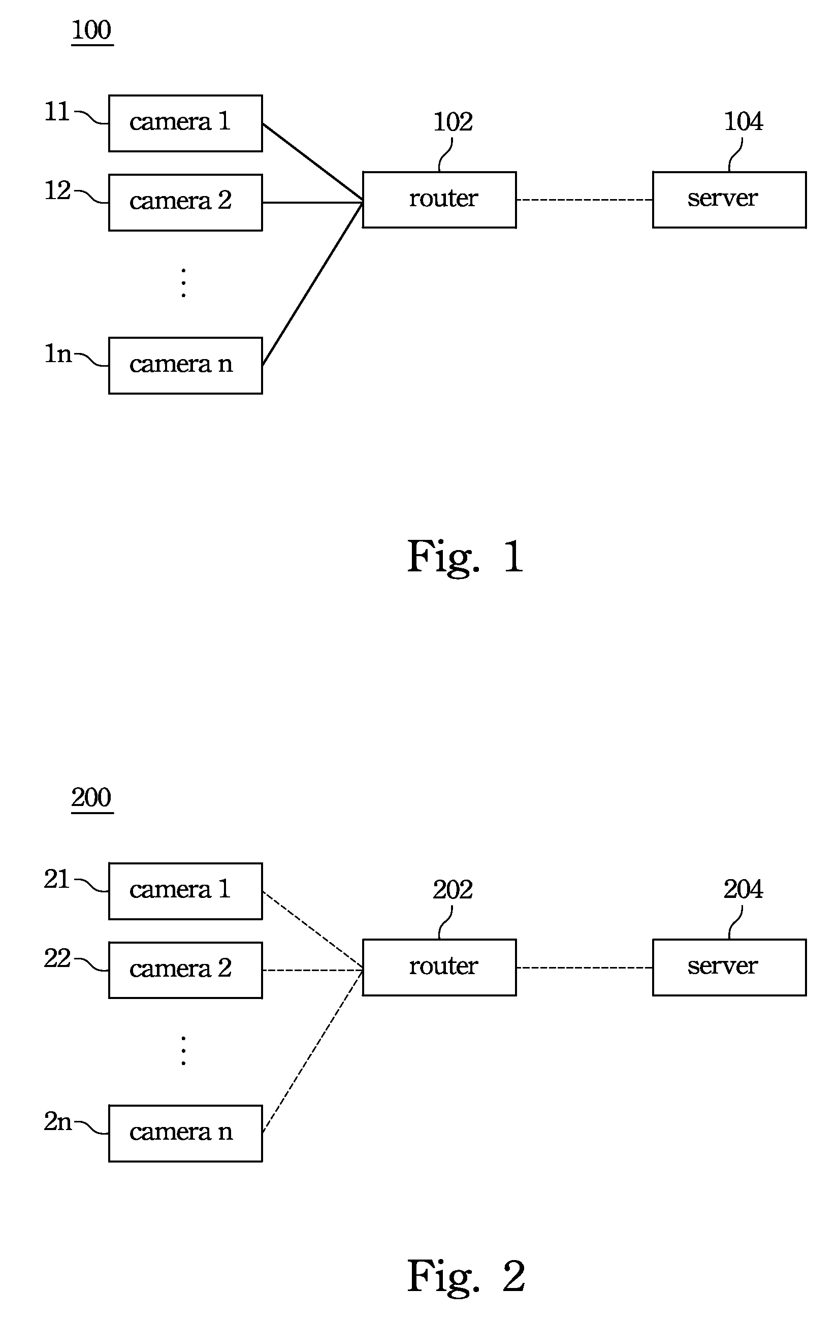
[0019]FIG. 1 is a system for remote monitoring and surveillance according to this invention. Refer to FIG. 1. The system 100 comprises a plurality of cameras 11, 12, . . . and 1n, a router 102, and a server 104. Cables individually connect the cameras 11, 12, . . . and 1n to the router 102. Wherein the cable communication protocol is either Universal Serial Bus (USB), HomePlug, Power Line Communication (PLC), or combinations thereof. The router 102 is connected to the server 104 through a wireless connection. The wireless communication protocol used to establish the wireless connection between the server and the router is either 3G, 3.5G, 4G, WiMax, WiFi, HSUPA, HSPA, LTE, or combinations thereof. The cameras 11, 12, . . . and 1n feature the following automatic functions: aperture adjustment, shutter adjustment, exposure adjustment, focus adjustment, white balance adjustment, night-vision mode, zoom-in, zoom-out, turning on lights of the cameras, switching to one of the cameras, rot...

second embodiment

[0022]FIG. 2 is a system for remote monitoring and surveillance according to this invention. Refer to FIG. 2. The system 200 comprises a plurality of cameras 21, 22, . . . and 2n, a router 202, and a server 204. The cameras 21, 22, . . . and 2n are wirelessly connected with the router 202 using short-ranged wireless communication protocol separately. Wherein, the short-range wireless communication protocol is either WiFi (802.11 series—802.11g, 802.11b, 802.11a, 802.11n etc.), Bluetooth, Ultra-wideband (UWB), ZigBee, or combinations thereof.

[0023]The router 202 is connected to the server 204 through a wireless connection. The wireless communication protocol used to establish the wireless connection between the server 204 and the router 202 is either 3G, 3.5G, 4G, WiMax, WiFi, HSUPA, HSPA, LTE, or combinations thereof. The cameras 21, 22, . . . and 2n feature the following automatic functions: aperture adjustment, shutter adjustment, exposure adjustment, focus adjustment, white balan...

third embodiment

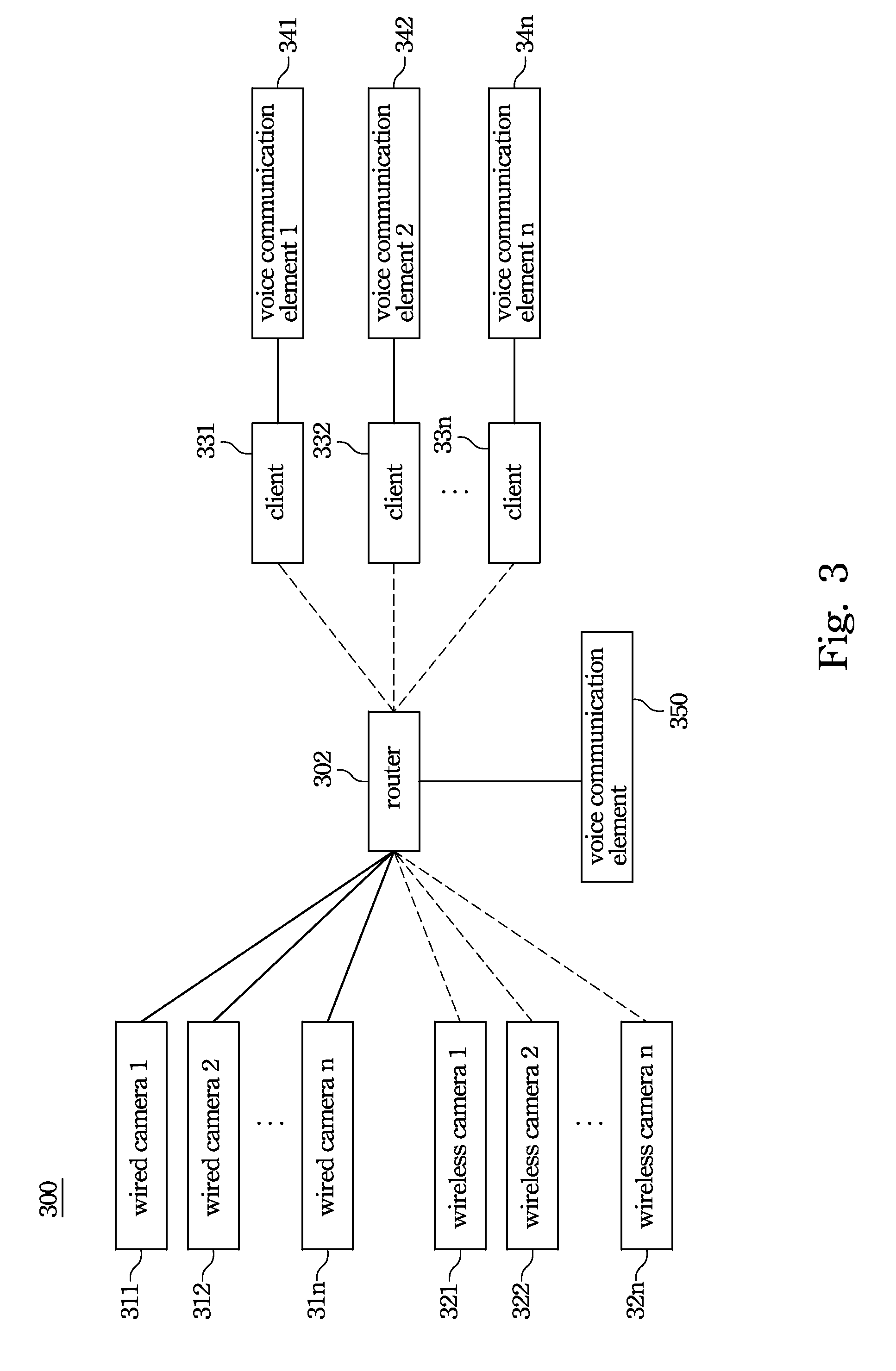
[0026]FIG. 3 is a system for remote monitoring and surveillance according to this invention. Refer to FIG. 3. The system 300 comprises a plurality of wired cameras 311, 312, . . . and 31n, a plurality of wireless cameras 321, 322, . . . and 32n, a plurality of clients 331, 332, . . . and 33n, a plurality of voice communication elements 341, 342, . . . 34n, 350 and a router 302. The wired cameras 311, 312, . . . and 31n are connected with the router 302 through wires using a wired cable communication protocol. Wherein the wired cable communication protocol is either Universal Serial Bus (USB), HomePlug, Power Line Communication (PLC), or combinations thereof. The cameras 321, 322, . . . and 32n are wirelessly connected with the router 302 using short-ranged wireless communication protocol separately. Wherein, the short-ranged wireless communication protocol is either WiFi (802.11 series—802.11g, 802.11b, 802.11a, 802.11n etc.), Bluetooth, Ultra-wideband (UWB), ZigBee, or combinations...


PUM


Abstract

A system for remote monitoring and surveillance is disclosed in this invention. The system comprises a plurality of cameras, a router, and a server. The cameras are connected with the router separately through a wired or wireless communication protocol. The router is connected with the server through a wireless communication protocol. The cameras capture scenes and convert the captured scenes into a plurality of image signals. The router uses a communication protocol to connect with the cameras, and the router transmits the image signals by a first wireless communication protocol. The server receives the image signals by the first wireless communication protocol, processes the image signals to obtain first images, and displays the first images. A method for remote monitoring and surveillance is also disclosed in this invention.

Description

CROSS-REFERENCE TO RELATED APPLICATION[0001]This application claims the priority benefit of U.S. Provisional Application Ser. No. 60 / 940,366, filed May 25, 2007, the full disclosures of which are incorporated herein by reference.BACKGROUND[0002]1. Field of Invention[0003]The present invention relates to a method and system for monitoring and surveillance. More particularly, the present invention relates to a method and system for remote monitoring and surveillance.[0004]2. Description of Related Art[0005]There is a strong need for both stationary and mobile remote monitoring and surveillance. For example, when an event happens, the commander in the police station has to see remotely through cameras installed on a pre-arrived police car to know what has actually happened at the event scene. In addition, the commander mentioned above also has to see remotely through different cameras installed on a pre-arrived police car to know more about the surroundings of the event scene.[0006]Ano...

Claims


Application Information

Patent Timeline
Patent Type & Authority Applications(United States)
IPC IPC(8): H04N7/18
CPCG08B13/19656H04N7/181G08B25/009
Inventor KUO, WEN-YICHUANG, LI-CHUNGLEONG, UN PIOYU, JUI-MINGWU, CHANG-HAN
Owner BANDRICH
Why Eureka
Try Eureka