Automatically configuring vacuum contactor

a technology of automatic configuration and contactor, which is applied in the direction of magnets, magnets, instruments, etc., can solve the problems of time-consuming, complex configuration of contactor controllers for different vacuum contactor altitudes, and upset forces balance, and achieve the effect of superior coil actuation

Active Publication Date: 2009-02-26
ROCKWELL AUTOMATION TECH
View PDF4 Cites 12 Cited by
  • Summary
  • Abstract
  • Description
  • Claims
  • Application Information

AI Technical Summary

Benefits of technology

[0021]It is thus a feature of one embodiment of the invention to permit sophisticated, empirically derived power adjustments unique to a particular coil, providing

Problems solved by technology

This balance of forces is upset if the vacuum contactor is moved to a different altitude having a different atmospheric pre

Method used


Image

  • Automatically configuring vacuum contactor
  • Automatically configuring vacuum contactor
  • Automatically configuring vacuum contactor

Examples


Embodiment Construction

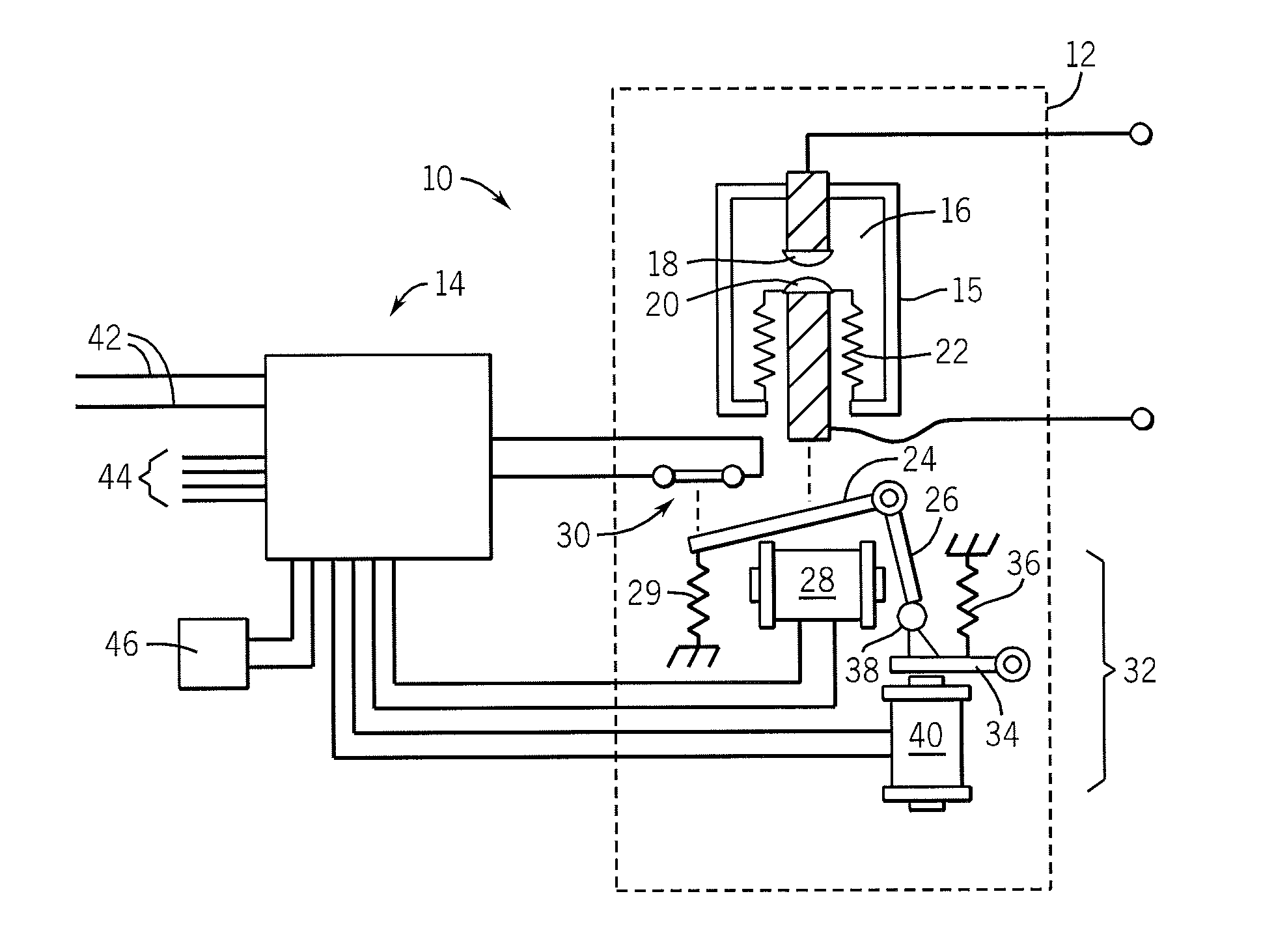
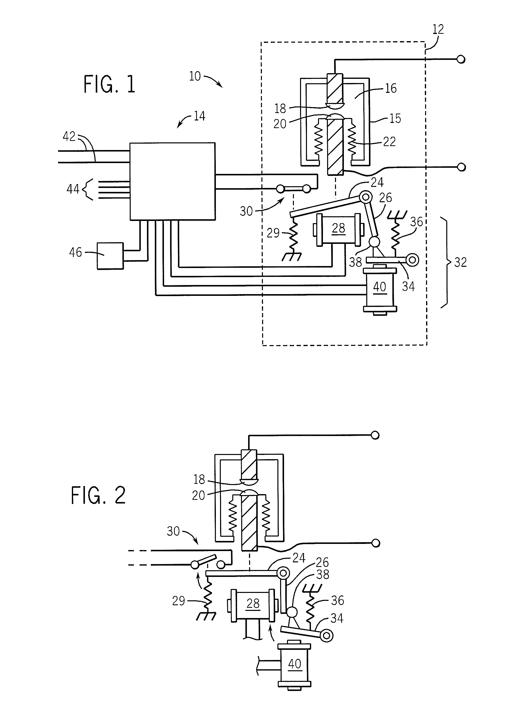
[0034]Referring now to FIG. 1, a vacuum contactor system 10, providing an example electromechanical switch system suitable for use with the present invention, includes a vacuum contactor 12 and a vacuum contactor controller 14.

[0035]As is generally understood in the art, the vacuum contactor 12 may include one or more vacuum bottles 15 providing a sealed evacuated chamber 16. Within the chamber 16 are two contacts: a stationary contact 18 fixed with respect to the vacuum bottle 15, and a movable contact 20 attached to the vacuum bottle 15 by means of a bellows 22.

[0036]The bellows 22 allows axial motion of the movable contact 20 toward and away from the stationary contact 18 under the influence of a pivoting armature 24 attached to the movable contact 20 through a biasing spring (not shown).

[0037]The armature 24 is raised or lowered by attraction between an armature tab 26 and a pole of a first electromagnet 28. In operation, the armature 24 is moved to a lowered position, separatin...


PUM


Abstract

A controller for a vacuum contactor or the like measures barometric pressure and provides a short impedance characterizing pulse to the coils of the vacuum contactor coils to assess proper operating conditions of the coils and to check for coil or sensor faults.

Description

CROSS-REFERENCE TO RELATED APPLICATIONS[0001]--STATEMENT REGARDING FEDERALLY SPONSORED RESEARCH OR DEVELOPMENT[0002]--BACKGROUND OF THE INVENTION[0003]The present invention relates to electromagnetically controlled switches, such as relays and contactors, and in particular to an improved controller for vacuum contactors.[0004]Vacuum contactors are electrically controlled switches used for interrupting high power circuits. In a vacuum contactor, a pair of contacts are enclosed inside a vacuum-tight bottle. One of the contacts is fixed to an end of the bottle and the other contact may be moved by means of a bellows toward and away from the fixed contact under the influence of an electrical solenoid. The vacuum surrounding the contacts helps suppress an arc formed when a circuit is interrupted.[0005]“Electrically-held” vacuum contactors, as the name suggests, hold the contacts in a closed position by continuously applying a holding current applied to the electrical solenoid. Typically ...

Claims


Application Information

Patent Timeline
IPC IPC(8): H01H47/22G01R31/72
CPCH01H33/666H01H47/00H01H47/02H01F7/1844G01R31/3274G01R31/06H01H2047/009G01R31/72
Inventor MACLENNAN, DAVID SCOTT S.
Owner ROCKWELL AUTOMATION TECH
Why Eureka
Try Eureka