Holey fiber and method of manufacturing the same

a technology of hole fiber and hole fiber, which is applied in the field of hole fiber and a method of manufacturing the same, can solve the problems of glass defect, air hole shape disadvantageous deformation, and stress applied to the core region and the air hole,

Inactive Publication Date: 2009-02-26
FURUKAWA ELECTRIC CO LTD
View PDF4 Cites 29 Cited by
  • Summary
  • Abstract
  • Description
  • Claims
  • Application Information

AI Technical Summary

Benefits of technology

[0012]According to another aspect of the present invention, there is provided a method of manufacturing a holey fiber including a core region and a cladding region surrounding the core region and having air holes arranged around the core region. The method includes forming a preform by arranging a core rod at a center of a jacket tube and inner capillary tubes around the core rod; and drawing the preform. Viscosities of the core rod and the inner capillary tubes are lower than a viscosity of the jacket tube.

Problems solved by technology

Shapes of the air holes can disadvantageously deform during the drawing process.
However, if the drawing process is performed at a low temperature, stress is applied to the core region and the air holes due to excess tension generated in the drawing process.
Such stress can lead to glass defect and distortion of surfaces of the air holes, which in turn leads to increase in transmission loss.
Thus, more complicated manufacturing processes are necessary.

Method used


Image

  • Holey fiber and method of manufacturing the same
  • Holey fiber and method of manufacturing the same
  • Holey fiber and method of manufacturing the same

Examples


Embodiment Construction

[0024]Exemplary embodiments of the present invention are explained in detail below with reference to the accompanying drawings. The present invention is not limited to the below embodiments.

[0025]Silica glass without dopant is referred to as pure silica glass in this document. Furthermore, bending loss is calculated under such a condition that an optical fiber is wound 16 times at a bending diameter of 20 millimeters. Moreover, a cut-off wavelength λc defined by International Telecommunication Union Telecommunication Standardization Sector (ITU-T) G.650.1 is employed. Other terms and methods are also used based on definitions and test methods defined by ITU-T G.650.1 unless otherwise specified in this document.

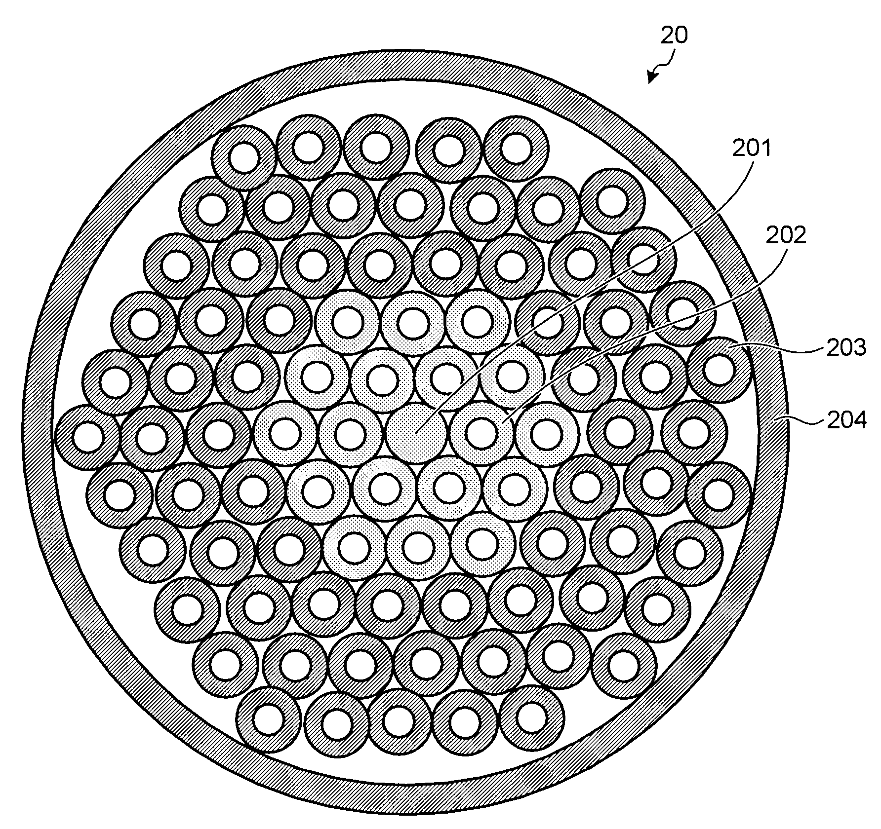
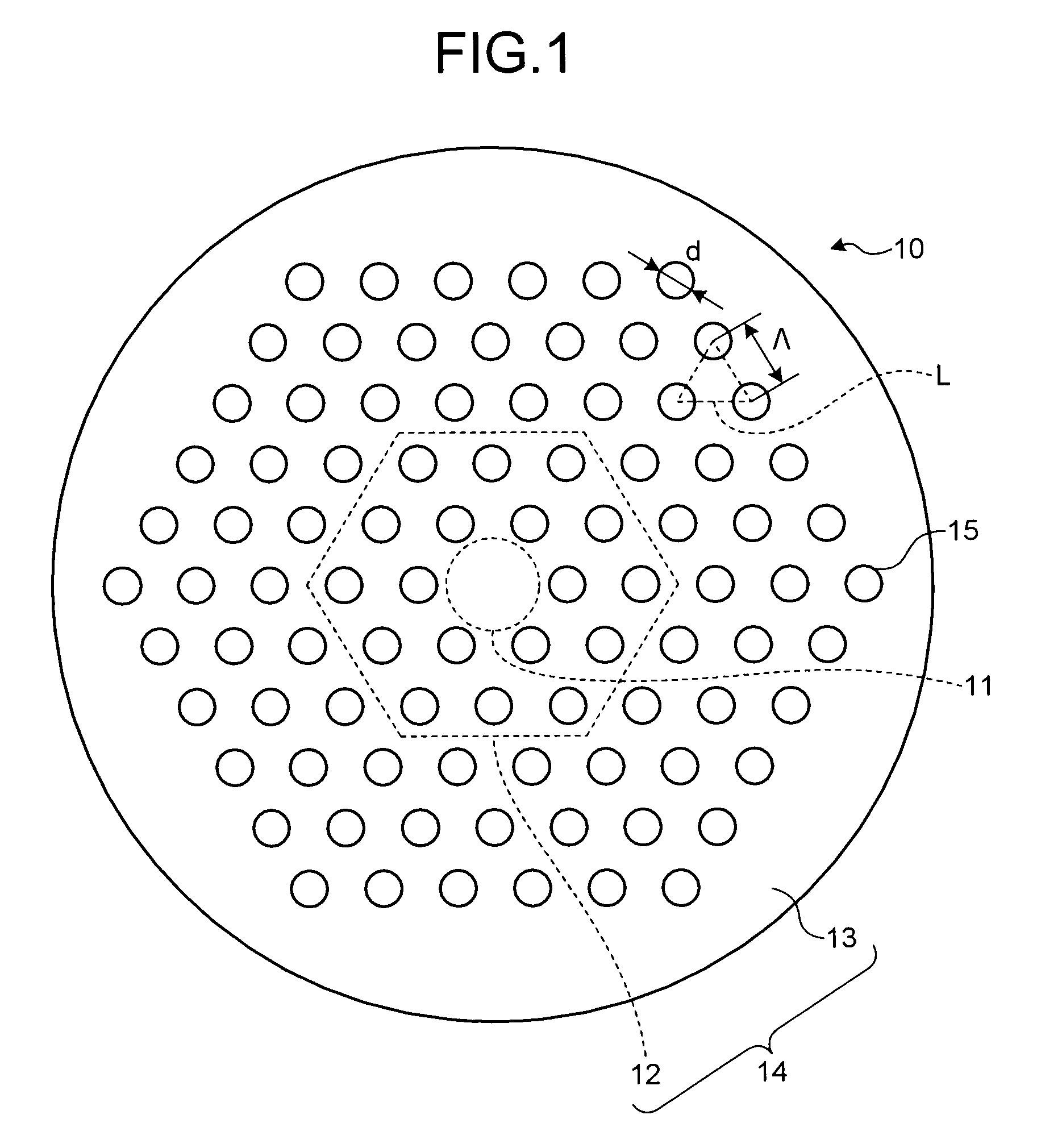
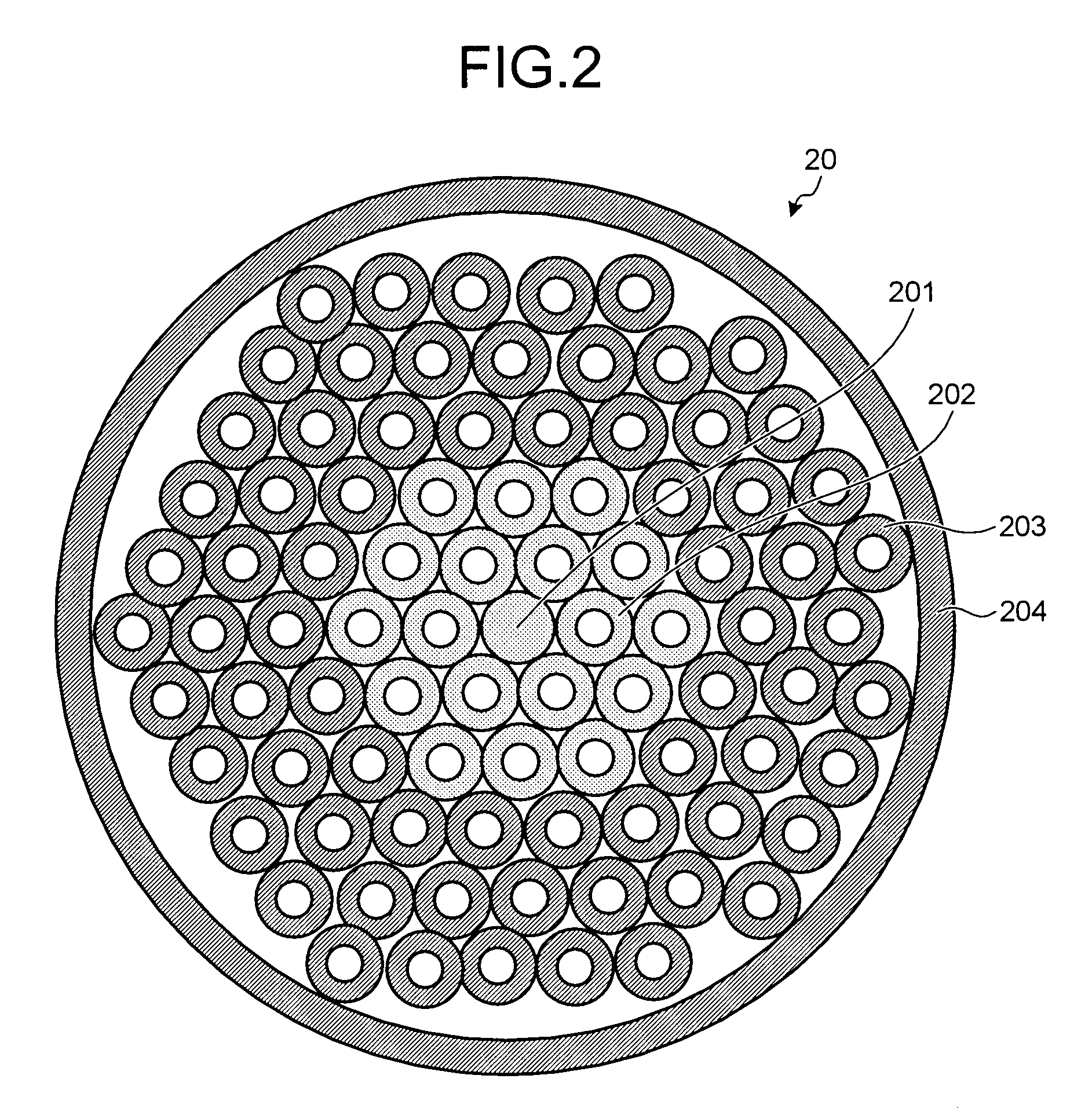
[0026]FIG. 1 is a schematic diagram of a holey fiber 10 according to an embodiment of the present invention. The holey fiber 10 includes a core region 11 at a center of the holey fiber 10 and a cladding region 14 surrounding the core region 11. The cladding region 14 includes ...


PUM

PropertyMeasurementUnit
viscositiesaaaaaaaaaa
temperatureaaaaaaaaaa
hole diameteraaaaaaaaaa

Abstract

A holey fiber includes a core region and a cladding region surrounding the core region and having air holes arranged around the core region. The cladding region includes an inner cladding layer surrounding the core region and an outer cladding layer surrounding the inner cladding layer. Furthermore, viscosities of the core region and the inner cladding layer are set lower than a viscosity of the outer cladding layer.

Description

BACKGROUND OF THE INVENTION[0001]1. Field of the Invention[0002]The present invention relates to a holey fiber and a method of manufacturing the same.[0003]2. Description of the Related Art[0004]A holey fiber is an optical fiber having air holes arranged in a periodic manner in a cladding region. The cladding region surrounds a core region. The cladding region has reduced average refractive index because of the presence of the air holes so that a light passes almost entirely through the core region because of the total reflection of the light.[0005]Because the refractive index of holey fibers can be controlled by controlling various parameters of the air holes, the holey fibers can realize unique properties that can not be realized in the other optical fibers such as endlessly single mode (ESM) and anomalous dispersion at a short wavelength. The ESM means that a cut-off wavelength is not present and a light is transmitted in a single mode at all wavelengths. With the ESM, it is poss...

Claims


Application Information

Patent Timeline
Patent Type & Authority Applications(United States)
IPC IPC(8): G02B6/02G02B6/00C03B7/01
CPCC03B37/02781C03B2201/08C03B2201/12C03B2201/31C03B2203/14G02B6/02361C03B2203/23C03B2203/42G02B6/02019G02B6/02266G02B6/02333C03B2203/22Y02P40/57
Inventor MUKASA, KAZUNORISUGIZAKI, RYUICHI
Owner FURUKAWA ELECTRIC CO LTD
Why Eureka
Try Eureka