Swing drive system for construction machine

Active Publication Date: 2009-02-26
HITACHI CONSTR MASCH CO LTD
View PDF2 Cites 26 Cited by
  • Summary
  • Abstract
  • Description
  • Claims
  • Application Information

AI Technical Summary

Benefits of technology

[0007]It is an object of the present invention is to provide a swing drive system for a construction machine which can execute operation intended by an operator and enhances safety.
[0009]With such a configuration, operation intended by an operator can be enabled and safety can be enhanced.
[0013](5) In the above (1), preferably, the swing drive system includes an output adjustment dial which can change output, and the control means reduces a value of the acceleration torque in proportion to a command value of the output adjustment dial.EFFECT OF THE INVENTION

Problems solved by technology

Thus, there arises a problem in that operation intended by an operator cannot be executed.

Method used


Image

  • Swing drive system for construction machine
  • Swing drive system for construction machine
  • Swing drive system for construction machine

Examples


first embodiment

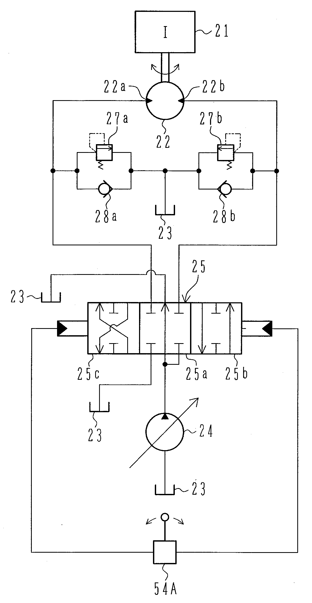
[0043]A description will hereinafter be made of the configuration and operation of a swing drive system for a construction machine according to the present invention with reference to FIGS. 1 to 5.

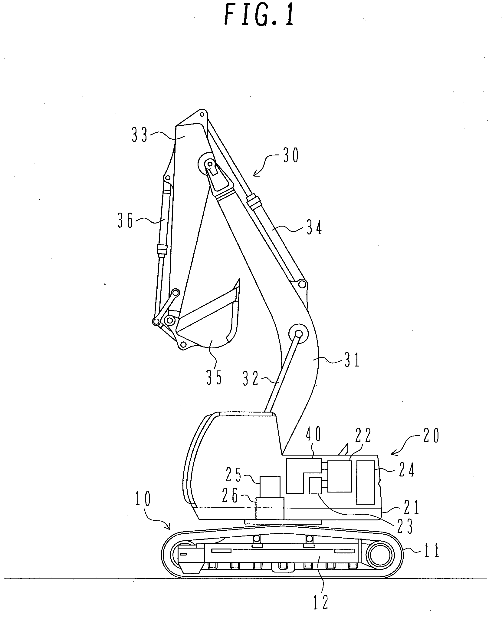
[0044]A configuration of the construction machine using the swing drive system for a construction machine according to the present embodiment is described with reference to FIG. 1. The construction machine is described taking a excavator as an example.

[0045]FIG. 1 is a lateral view illustrating the configuration of the construction machine using the swing drive system according to the first embodiment of the present invention.

[0046]A undercarriage 10 includes a pair of crawlers 11 and a pair of crawler frames 12 (one of them is depicted in the figure). The crawlers 11 are independently controllably driven by a pair of respective travel-purpose electric motors 13, 14 described later with FIG. 2, speed-reducing mechanisms therefor and the like.

[0047]An upperstructure 20 includes a main frame...

second embodiment

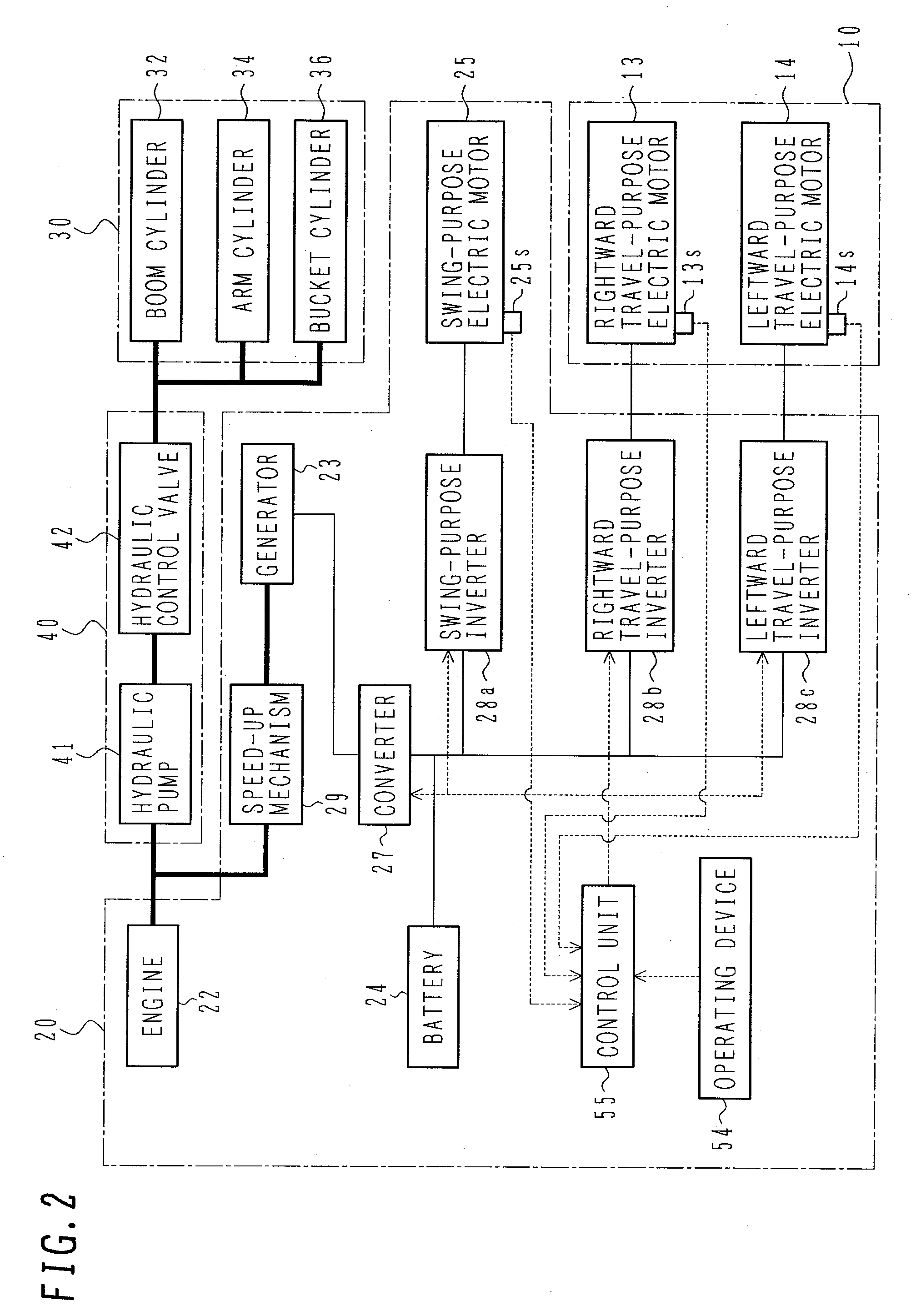
[0081]A description is next made of the configuration and operation of a swing drive system for a construction machine according to the present invention with reference to FIG. 6. The configuration of the construction machine of the present embodiment is the same as shown in FIG. 1. In addition, the configuration of the drive control device of the construction machine including the swing drive system according to the present embodiment is the same as shown in FIG. 2.

[0082]FIG. 6 is a system block diagram illustrating the configuration of a swing drive system for the construction machine according to the second embodiment. Note that the same reference numerals as in FIGS. 1 to 3 denote the same portions.

[0083]Swing control means 55B, included in the control unit 55 shown in FIG. 2, is control means for exercising swing control. The swing control means 55B receives a lever control input signal Pisw from the swing control lever device 54A in the operating device 54 shown in FIG. 2 and ...

third embodiment

[0092]A description is next made of the configuration and operation of a swing drive system for a construction machine according to the present invention with reference to FIG. 7. The configuration of the construction machine of the present embodiment is the same as shown in FIG. 1. In addition, the configuration of the drive control unit of the construction machine including the swing drive system according to the present embodiment is the same as shown in FIG. 2.

[0093]FIG. 7 is a system block diagram illustrating the configuration of a swing drive system for the construction machine according to the third embodiment. Note that the same reference numerals as in FIGS. 1 to 3 denote the same portions.

[0094]Swing control means 55A′, included in the control unit 55 shown in FIG. 2, is control means which exercises swing control. The swing control means 55A′ includes a maximum dial angle output device 42, a divider 43 and a multiplier 44 in addition to the configuration of the swing con...


PUM


Abstract

A swing drive system for a construction machine enhances safety for an operator. A swing control means 55A has a lever input amount-torque table 11 and an actual rotating speed-torque table 13. Based on a lever input amount and an actual rotating speed of an electric motor, the tables are used to derive torque values. A minimum value of the torque values is taken as the acceleration torque. The swing control means 55A further has a lever input amount-meter-out restriction area table 15 and an actual rotating speed-relief torque table 119. Based on the lever input amount and the actual rotating speed of the electric motor, a meter-out restriction area is derived from the lever input amount-meter-out restriction area table and the actual rotating speed to calculate a meter-out torque. A minimum value of the meter-out torque and relief torque is taken as the braking torque.

Description

TECHNICAL FIELD[0001]The present invention relates to a swing drive system for a construction machine and particularly to a swing drive system for a construction machine using an electric motor as an actuator.BACKGROUND ART[0002]Hydraulic actuators have widely been used in the field of construction machine because the component can be reduced in size and weight irrespective of its output power. The hydraulic actuator has lower energy efficiency than the electric actuator; therefore, mounting the electric actuator has recently been studied. In particular, an actuator that drivingly swings the upperstructure of a construction machine relative to the undercarriage is frequently used and is of a rotary type. Therefore, it is effective to replace the hydraulic actuator with an electric actuator.[0003]A swing drive system using an electric actuator was experimentally manufactured and researched. However, it was revealed that a problem with safety is likely to occur if the swing drive syst...

Claims


Application Information

Patent Timeline
IPC IPC(8): E02F9/22G06F17/00
CPCE02F9/123F15B2211/7058E02F9/2025E02F9/2075E02F9/226E02F9/2296F15B21/087F15B2211/20523F15B2211/20546F15B2211/3116F15B2211/329F15B2211/50527F15B2211/5059F15B2211/6336F15B2211/6346E02F9/128E02F9/20E02F9/22F15B11/04
Inventor OOKI, TAKATOSHITANAKA, ATSUSHIWATANABE, YUTAKAOCHIAI, MASAM
Owner HITACHI CONSTR MASCH CO LTD
Why Eureka
Try Eureka