Gas Turbine Engine Systems and Related Methods Involving Multiple Gas Turbine Cores

a gas turbine engine and core technology, applied in the direction of engines, jet propulsion plants, machines/engines, etc., can solve the problems of engine operation that is much of the time in a non-optimal manner

Inactive Publication Date: 2009-03-05
RAYTHEON TECH CORP
View PDF24 Cites 37 Cited by
  • Summary
  • Abstract
  • Description
  • Claims
  • Application Information

AI Technical Summary

Problems solved by technology

Unfortunately, various design tradeoffs typically are made in order to accommodate such a broad range of requirements.
These tradeoffs oftentimes result in an engine that operates much of the time in a non-optimal manner.

Method used


Image

  • Gas Turbine Engine Systems and Related Methods Involving Multiple Gas Turbine Cores
  • Gas Turbine Engine Systems and Related Methods Involving Multiple Gas Turbine Cores
  • Gas Turbine Engine Systems and Related Methods Involving Multiple Gas Turbine Cores

Examples


Embodiment Construction

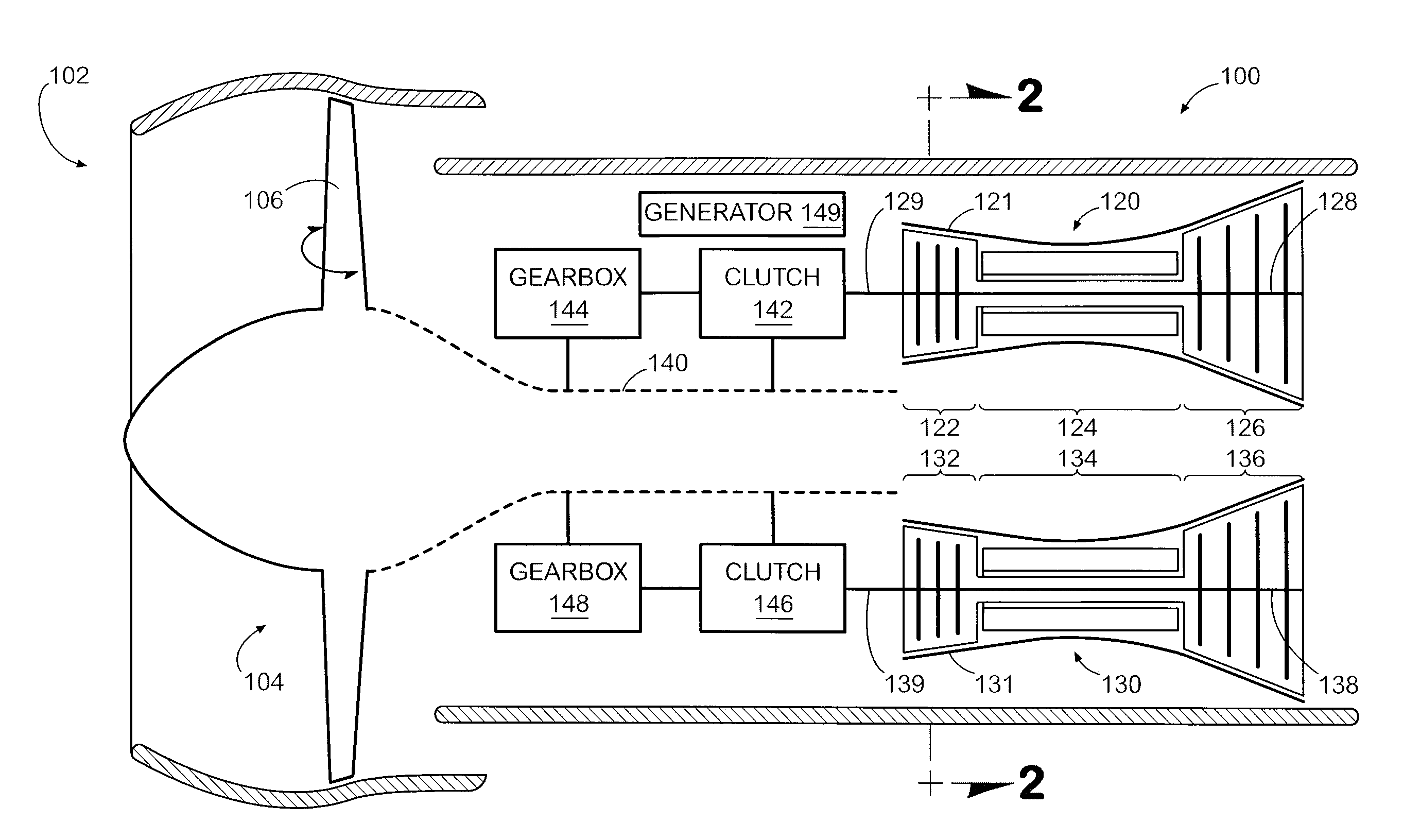
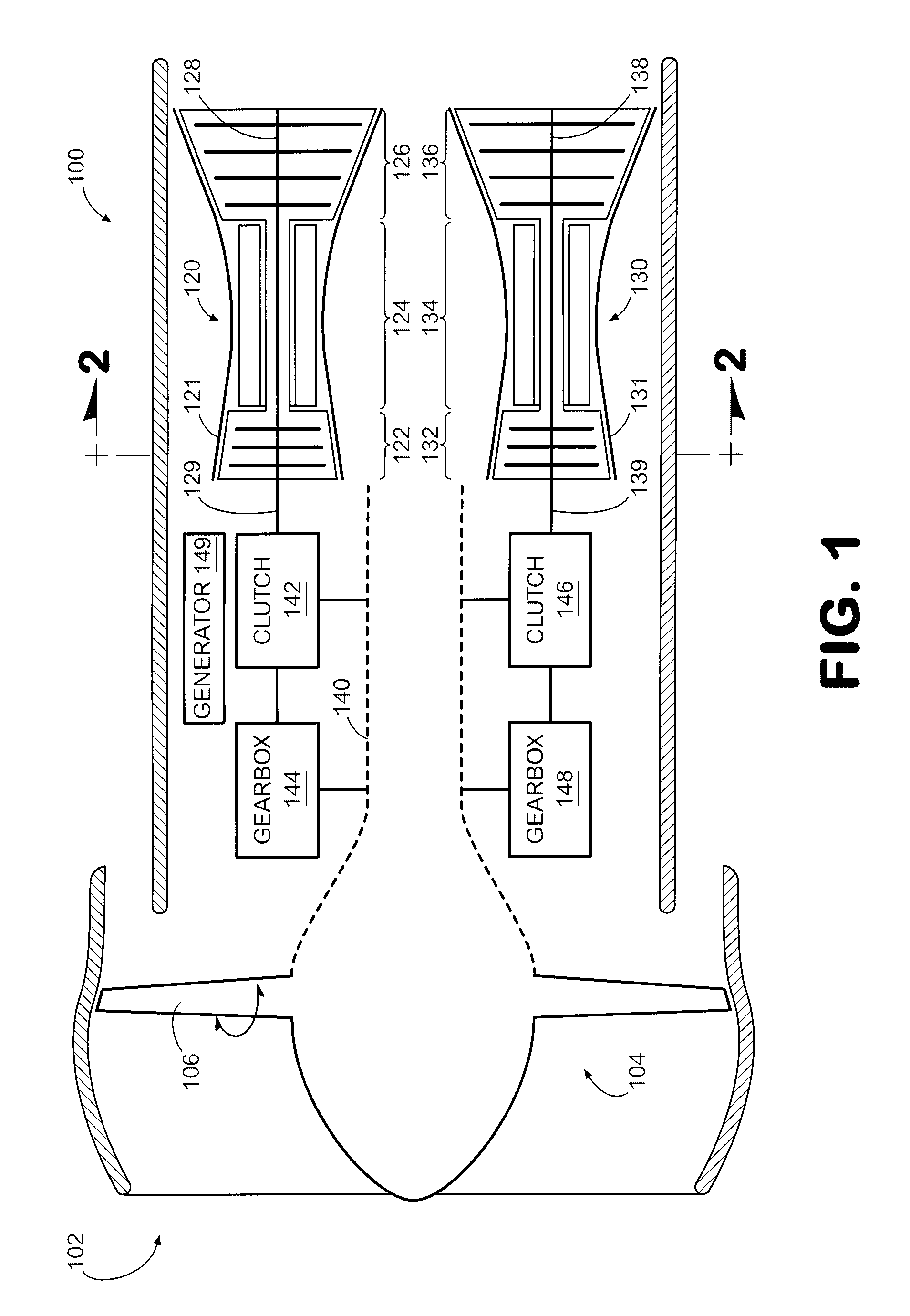
[0014]Gas turbine engine systems and related methods involving multiple gas turbine cores are provided, several representative embodiments of which will be described in detail. In this regard, FIG. 1 is a schematic diagram depicting an exemplary embodiment of a gas turbine engine.

[0015]As shown in FIG. 1, gas turbine engine 100 incorporates an inlet 102 that provides intake air to a blade assembly 104. In this embodiment, engine 100 is a turbofan, with the blade assembly being configured as a fan incorporating multiple variable pitch blades, e.g., blade 106. However, in other embodiments, the blade assembly could be a set of blades of a compressor of a turbojet, for example. Thus, the concepts described herein should not be construed as being limited to turbofans.

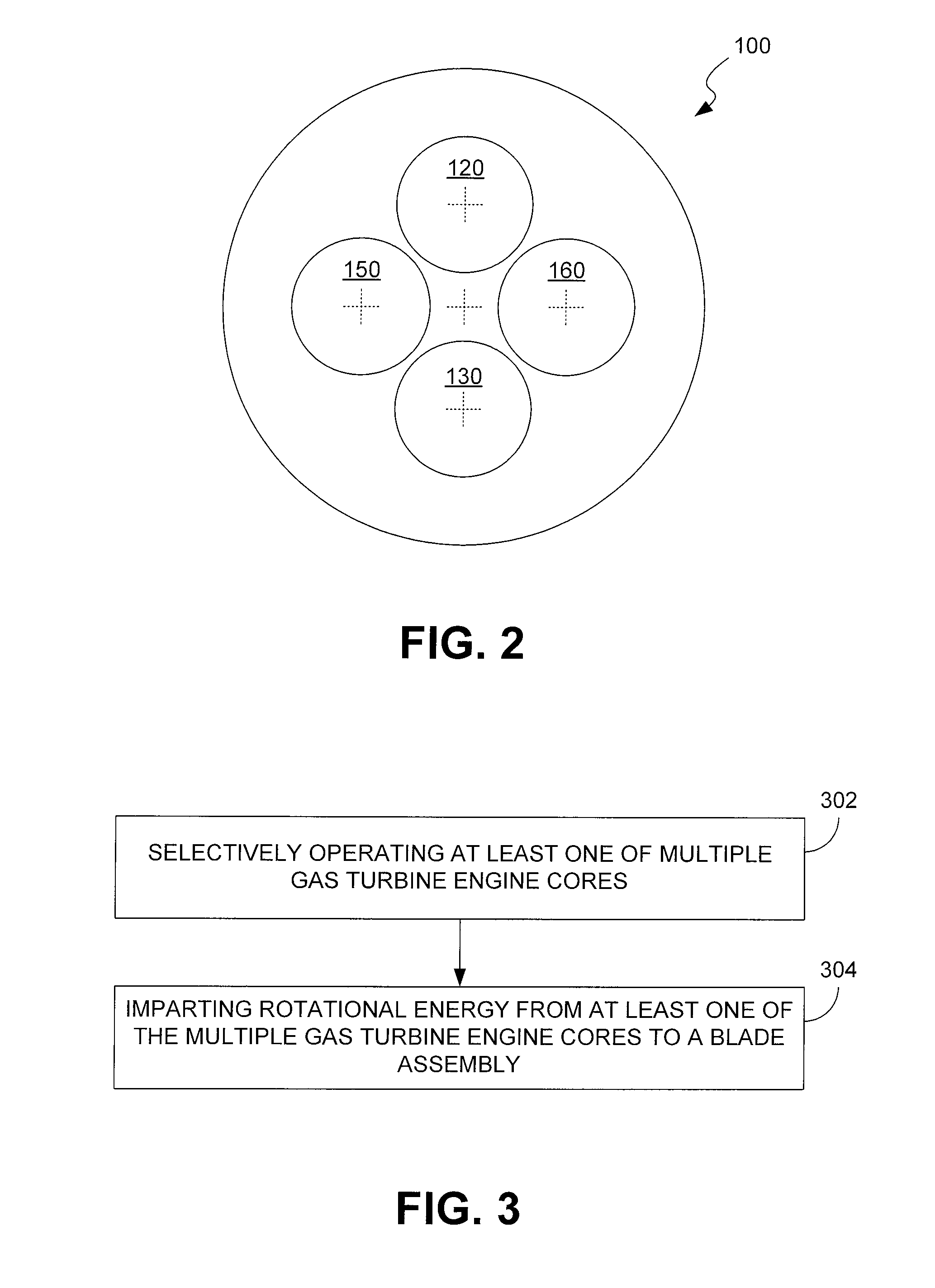
[0016]Downstream of the blade assembly are located multiple gas turbine cores. Specifically, four such gas turbine cores are used in this embodiment although only cores 120, 130 are shown for ease of illustration in FIG. 1....


PUM


Abstract

Gas turbine engine systems and related methods involving multiple gas turbine cores are provided. In this regard, a representative gas turbine engine includes: an inlet; a blade assembly mounted to receive intake air via the inlet; and multiple gas turbine cores located downstream of the blade assembly, each of the multiple gas turbine cores being independently operative in a first state, in which rotational energy is provided to rotate the blade assembly, and a second state, in which rotational energy is not provided to rotate the blade assembly.

Description

BACKGROUND[0001]1. Technical Field[0002]The disclosure generally relates to gas turbine engines.[0003]2. Description of the Related Art[0004]Gas turbine engines typically are designed to operate over a broad range of power settings in order to meet varying mission requirements. Unfortunately, various design tradeoffs typically are made in order to accommodate such a broad range of requirements. These tradeoffs oftentimes result in an engine that operates much of the time in a non-optimal manner.SUMMARY[0005]Gas turbine engine systems and related methods involving multiple gas turbine cores are provided. In this regard, an exemplary embodiment of a gas turbine engine comprises: an inlet; a blade assembly mounted to receive intake air via the inlet; and multiple gas turbine cores located downstream of the blade assembly, each of the multiple gas turbine cores being independently operative in a first state, in which rotational energy is provided to rotate the blade assembly, and a seco...

Claims


Application Information

Patent Timeline
Patent Type & Authority Applications(United States)
IPC IPC(8): F02K3/12
CPCF02C3/113F02K3/06F02K3/12F02C9/00F05D2240/40F05D2260/74F05D2220/76
Inventor ROBERGE, GARY D.
Owner RAYTHEON TECH CORP
Why Eureka
Try Eureka