Method and apparatus for converting energy in a moving fluid mass to rotational energy driving a transmission

a technology of moving fluid and transmission, applied in the direction of electrical apparatus, sea energy generation, engine fuction, etc., can solve problems such as affecting the function of the transmission system

Inactive Publication Date: 2009-08-27
PATTON ROLAND WAYNE
View PDF7 Cites 38 Cited by
  • Summary
  • Abstract
  • Description
  • Claims
  • Application Information

AI Technical Summary

Benefits of technology

[0009]Thus as may be seen by an understanding of the first and second embodiments of the present invention, it is the use of the weight, or other suspended weighted body, that enables the relative movement between the first, second and third bodies as the fluid mass moves or swells (or is otherwise elevated, rises and falls or such other hydraulic actuation) to drive the drive chain or other flexibl

Problems solved by technology

Again, the float floats on the exposed surface of the waves and, in applicant's opini

Method used


Image

  • Method and apparatus for converting energy in a moving fluid mass to rotational energy driving a transmission
  • Method and apparatus for converting energy in a moving fluid mass to rotational energy driving a transmission
  • Method and apparatus for converting energy in a moving fluid mass to rotational energy driving a transmission

Examples


Embodiment Construction

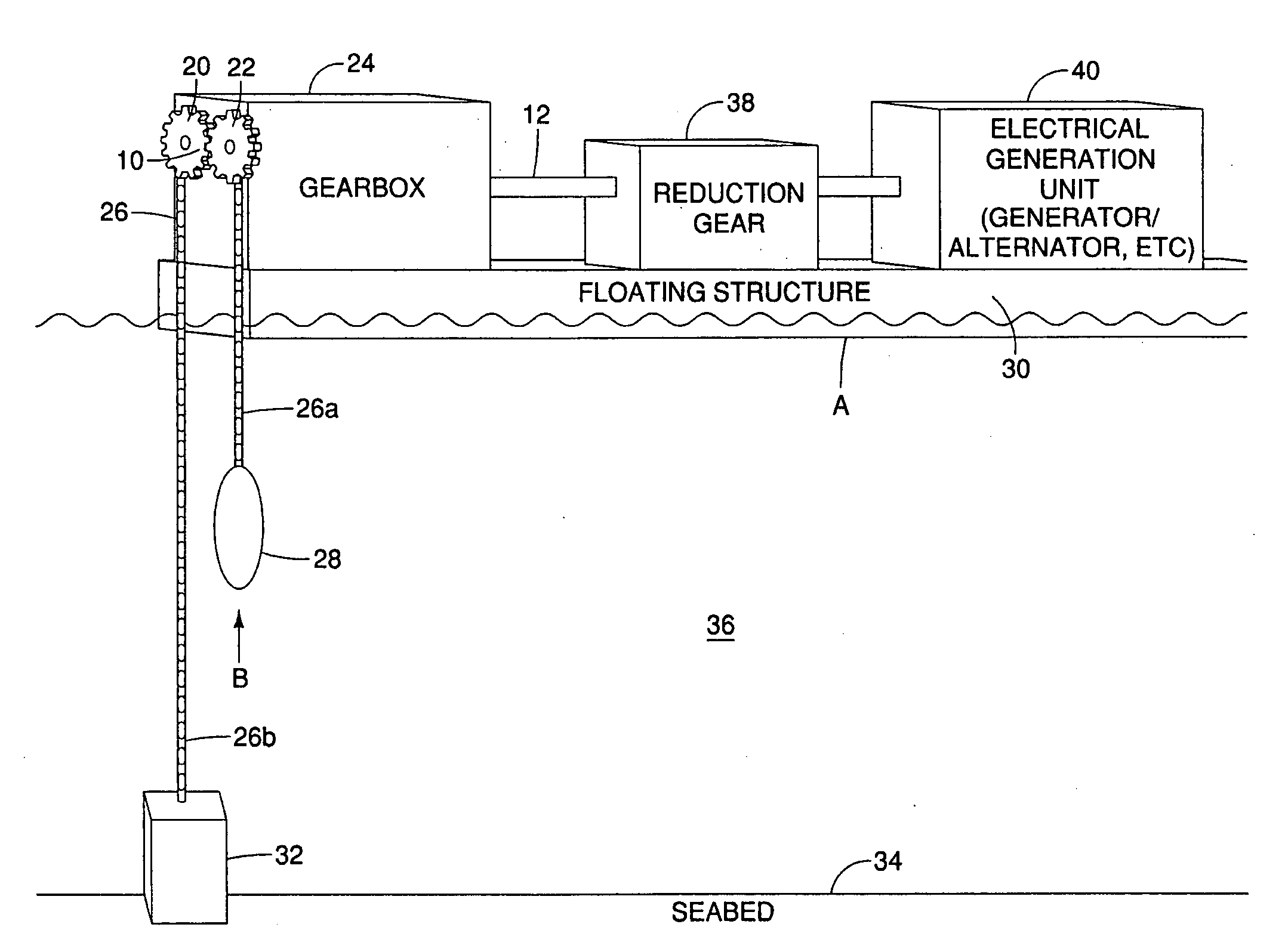
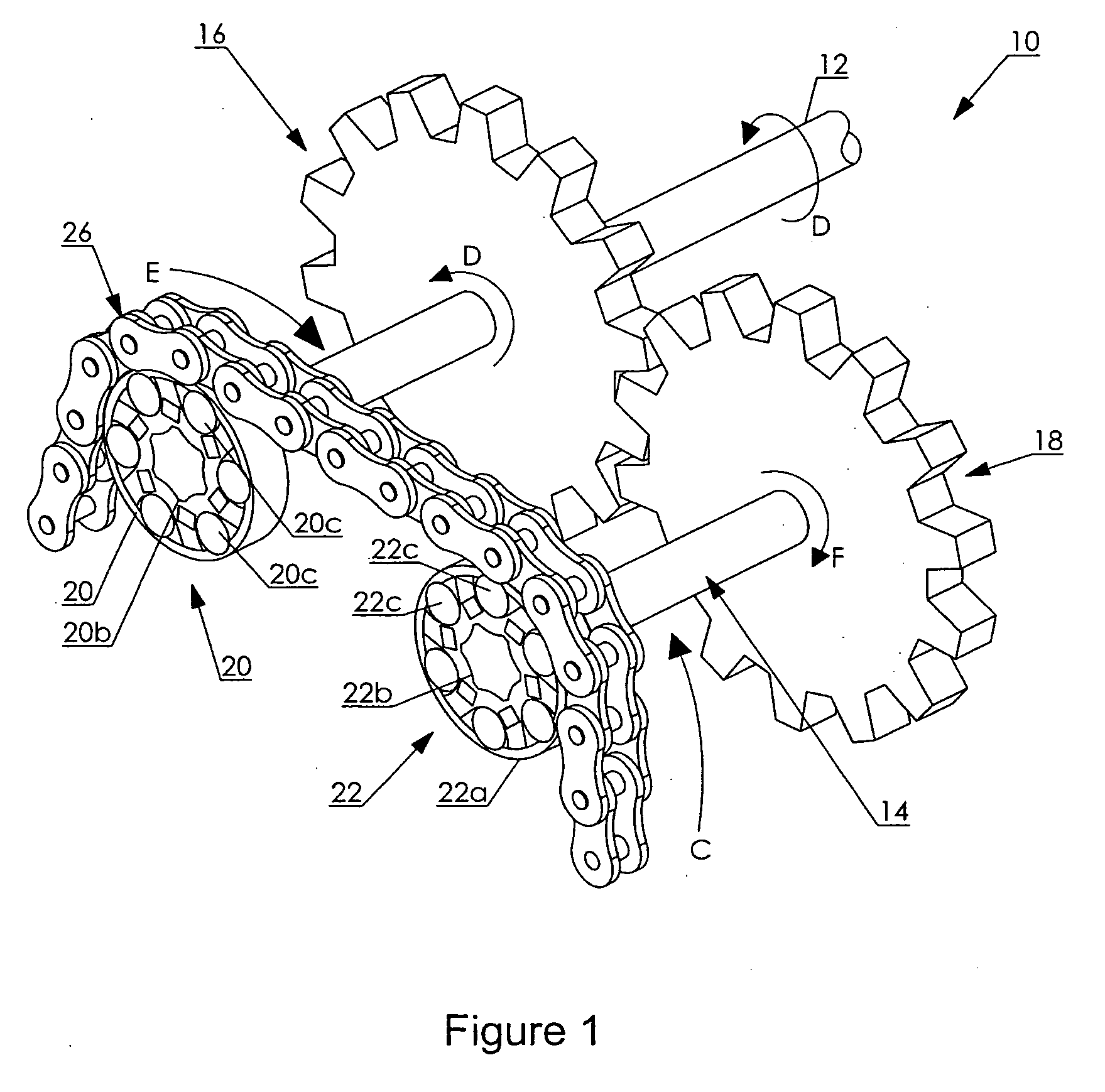
[0022]As seen in FIG. 1, in one embodiment, the transmission 10 includes a primary shaft 12 mounted in appropriate bearings (not shown), and an adjacent and parallel stub shaft or secondary shaft 14 also mounted in appropriate bearings (not shown). A pair of intermeshed gears 16 and 18 are mounted on shafts 12 and 14 respectively and intermeshed so that rotation of one causes rotation of the other. A pair of one-way clutches 20 and 22 are mounted onto the ends of shafts 12 and 14 respectively and in particular to the ends of those shafts which are exposed from a housing or gear box 24 as better seen by way of example in FIG. 2. As illustrated, one-way clutches 20 and 22 are, respectively, although generally referred to herein as clutches, a clockwise overrunning clutch and sprocket, and a counter clockwise over running clutch and sprocket.

[0023]As is known in the art, in the one form of one-way clutch which is illustrated, and which is not intended to be limiting, each clutch includ...


PUM


Abstract

Three bodies interact to drive a transmission having a pair of one-way clutches coupling a single length of drive chain or other elongate flexible member to an intermeshed pair of counter rotatable gears so as to drive a primary shaft in a single rotational direction. The three bodies are a fixed body, a floating body, and a suspended and usually submerged weighted body. The three bodies are interconnected by the single length of the elongate flexible member and are spaced apart there along. The weighted body is mounted at one end of the elongate flexible member. The primary shaft is mounted above the surface of a moving fluid mass to either the fixed or floating body. The end of the flexible member opposite to the weight is mounted to the other of the fixed or floating body.

Description

CROSS REFERENCE TO RELATED APPLICATION[0001]This application claims priority from U.S. Provisional Patent Application No. 61 / 064,262 filed Feb. 25, 2008 entitled. Method and Apparatus for Converting Energy in a Moving Fluid Mass to Rotational Energy Driving a Transmission, and from Canadian Patent Application No. 2,622,284 filed Feb. 25, 2008 entitled. Method and Apparatus for Converting Energy in a Moving Fluid Mass to Rotational Energy Driving a Transmission.FIELD OF THE INVENTION[0002]This invention relates to the field of motors for converting energy from ocean waves, tides or other moving bodies of water or other fluids to mechanical work, and in particular to converting the energy found in such moving fluid masses to rotational energy so as to drive a transmission which in turn may drive a generator or the like.BACKGROUND OF THE INVENTION[0003]As stated by Solell in U.S. Pat. No. 4,145,885 which issued Mar. 27, 1979 for a Wave Motor, it is known that the energy in the sea cons...

Claims


Application Information

Patent Timeline
IPC IPC(8): F03B13/18
CPCF03B13/1865F03B13/262Y02E60/17F05B2260/505Y02E10/38F05B2240/93Y02E10/30Y02E60/16
Inventor PATTON, ROLAND WAYNE
Owner PATTON ROLAND WAYNE
Why Eureka
Try Eureka