
Knife Sharpener System

a knife and blade technology, applied in the field of knife sharpeners, can solve the problems of increasing the time it takes to clean the knife sharpener, affecting the life of the knife sharpener, and affecting the sharpening effect of the knife blade, so as to achieve the effect of not rusting over time and quick sharpening the knife blad

Inactive Publication Date: 2009-03-05
FRIESEN BRETT A +2
View PDF11 Cites 8 Cited by
  • Summary
  • Abstract
  • Description
  • Claims
  • Application Information

AI Technical Summary

Benefits of technology

[0013]An object is to provide a knife sharpener system for efficiently and quickly sharpening a blade of a knife.
[0015]An additional object is to provide a knife sharpener system that is dishwasher safe.
[0016]A further object is to provide a knife sharpener system that does not rust over time.
[0017]Another object is to provide a knife sharpener system that includes a plurality of sharpening contact areas to quickly sharpen the blade of the knife.

Problems solved by technology

One nuisance is that many knife sharpeners leave behind a metal residue on the blade edges after sharpening thus causing the metal residue to come in contact with food if the blade isn't properly cleaned.
Another problem is that many knife sharpeners are not dishwasher safe thus increasing the time it takes to clean the knife sharpener.
A further problem with prior knife sharpeners is that the material of the knife sharpener may begin to rust over time, thus decreasing the life of the knife sharpener.
Also, knife sharpeners generally only include a single point of contact for the blade and generally only sharpen one side of the blade at one time, thus increasing the time it takes to sharpen the blade.

Method used


Image

  • Knife Sharpener System
  • Knife Sharpener System
  • Knife Sharpener System

Examples


Embodiment Construction

A. Overview

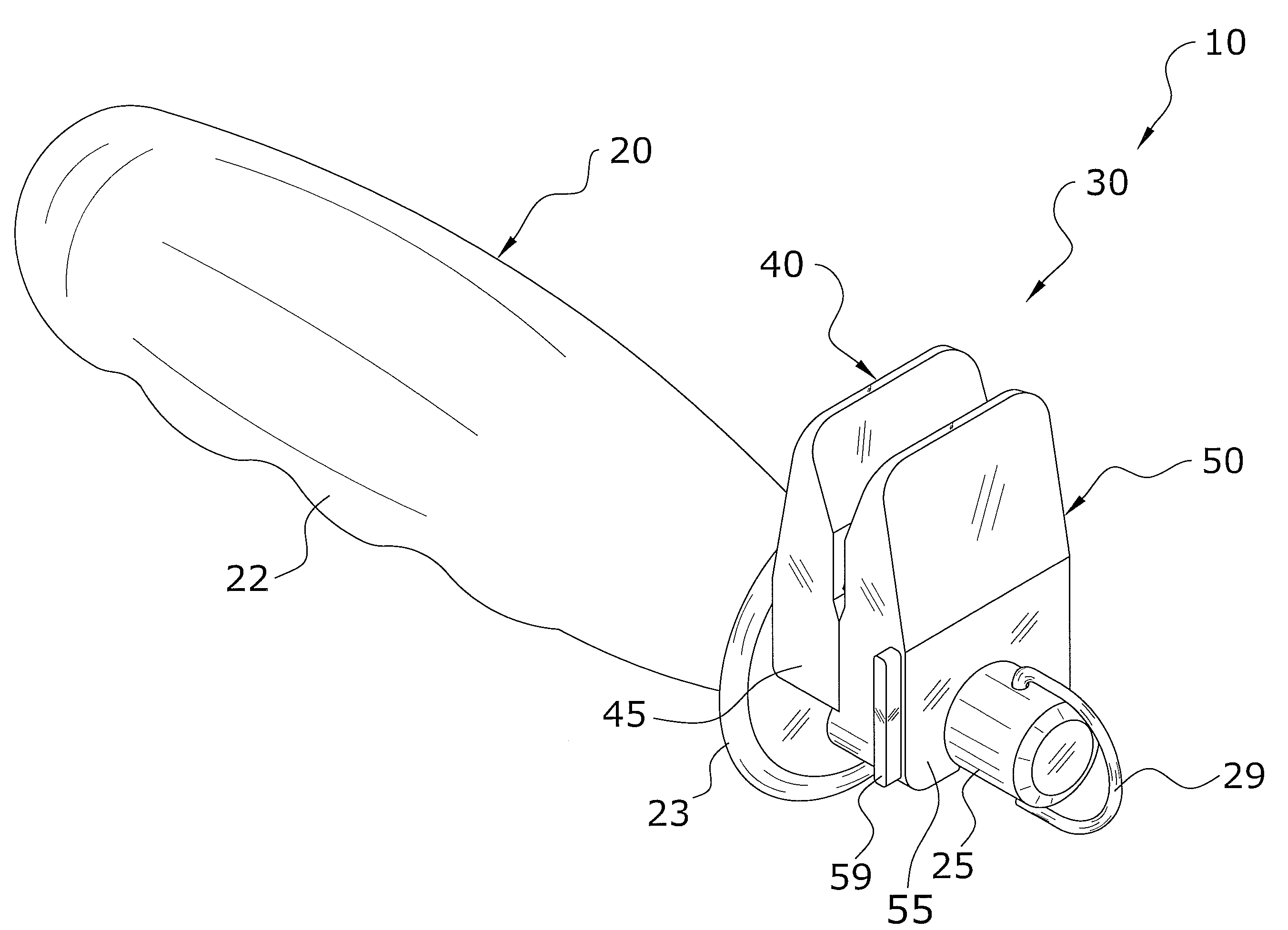
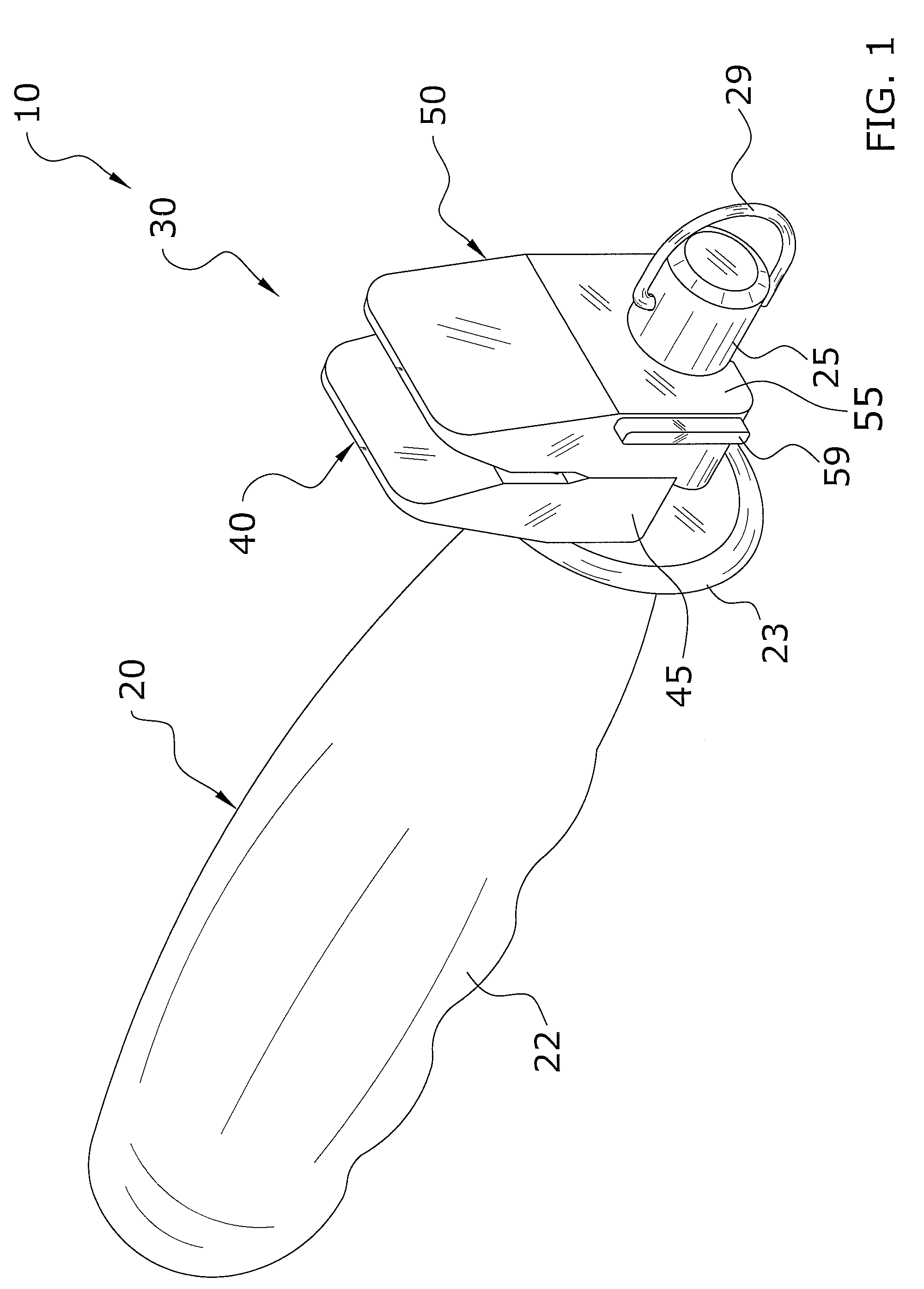
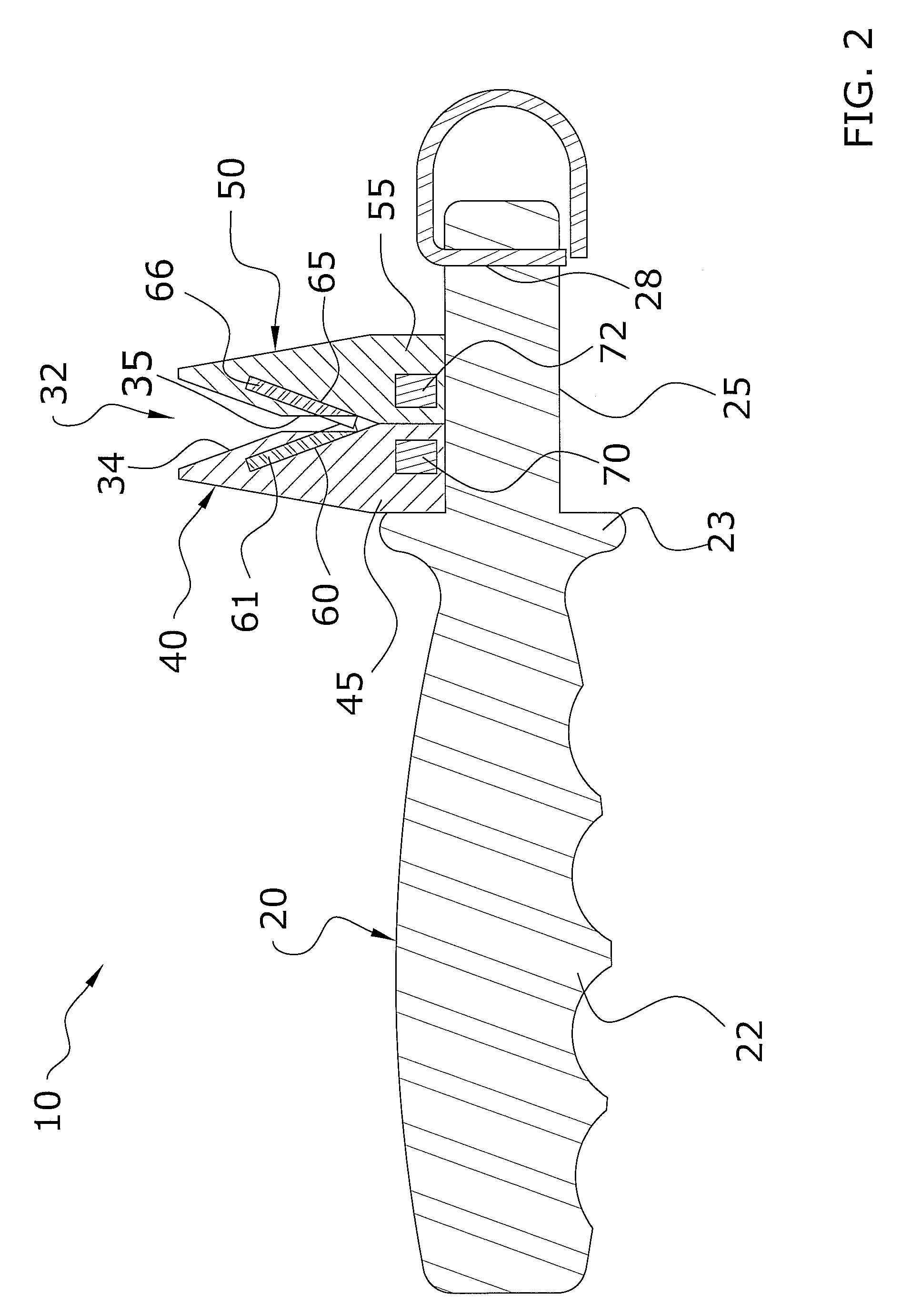
[0032]Turning now descriptively to the drawings, in which similar reference characters denote similar elements throughout the several views, FIGS. 1 through 10 illustrate a knife sharpener system 10, which comprises a support structure 20, a sharpening unit 30 including a retaining portion 36, wherein the sharpening unit 30 extends from the support structure 20, at least one sharpening member 60, 65 extending from the sharpening unit 30 and at least one magnet 70, 72 positioned within the sharpening unit 30, wherein the retaining portion 36 is positioned between the sharpening member 60, 65 and the magnet 70, 72 and wherein a metal residue 17 of a blade 12 is magnetically attracted to the retaining portion 36 via the magnet 70, 72.

B. Support Structure

[0033]The support structure 20 includes a handle 22 for a user to grasp while utilizing the present invention and also a support member 25 extending from the handle 22 to receive and secure the sharpening unit 30 as illustrat...


PUM


Abstract

A knife sharpener system for efficiently and quickly sharpening a blade of a knife. The knife sharpener system generally includes a support structure, a sharpening unit including a retaining portion, wherein the sharpening unit extends from the support structure, at least one sharpening member extending from the sharpening unit and at least one magnet positioned within the sharpening unit, wherein the retaining portion is positioned between the sharpening member and the magnet and wherein a metal residue of a blade is magnetically attracted to the retaining portion via the magnet.

Description

CROSS REFERENCE TO RELATED APPLICATIONS[0001]Not applicable to this application.STATEMENT REGARDING FEDERALLY SPONSORED RESEARCH OR DEVELOPMENT[0002]Not applicable to this application.BACKGROUND OF THE INVENTION[0003]1. Field of the Invention[0004]The present invention relates generally to knife sharpeners and more specifically it relates to a knife sharpener system for efficiently and quickly sharpening a blade of a knife.[0005]2. Description of the Related Art[0006]Any discussion of the prior art throughout the specification should in no way be considered as an admission that such prior art is widely known or forms part of common general knowledge in the field.[0007]Knife sharpeners have been in use for years. Typically, knife sharpeners are manufactured in various sizes and configurations and are utilized for creating or refining a sharp edge upon a blade (e.g. knife, etc.), tool or implement. Knife sharpeners may further be comprised of powered knife sharpeners (e.g. grinders, e...

Claims


Application Information

Patent Timeline
IPC IPC(8): B21K11/02
CPCB24D15/081
Inventor FRIESEN, BRETT A.LEBRASSEUR, MITCHEL T.MONCRIEF, KEN
Owner FRIESEN BRETT A
Learn More