
Portable air cleaner with improved multi-stage electrostatic precipitator

a multi-stage electrostatic precipitator and air cleaner technology, applied in the field of gas purification, can solve the problems of increasing the quantity of ozone, the cost of wires, and the typical production of ozone, so as to improve the functionality and performance of the system, reduce materials and manufacturing costs, and improve the effect of air delivery ra

Active Publication Date: 2019-01-15
LASKO OPERATION HLDG LLC
View PDF13 Cites 2 Cited by
  • Summary
  • Abstract
  • Description
  • Claims
  • Application Information

AI Technical Summary

Benefits of technology

The patent text describes an improved electrostatic precipitation air cleaner that reduces ozone and arcing issues associated with conventional technology. The improved air cleaner has multi-stage electrostatic precipitation filter systems that can clean an ordinary sized room while also reducing ozone naturally present in room air. Overall, the improved air cleaner has better functionality and performance while addressing the deficiencies of conventional technology.

Problems solved by technology

One drawback to conventional electrostatic precipitation room air cleaners is that they typically produce ozone.
Not only does the cost increase according to the number of wires employed, but the quantity of ozone also increases.
Another problem with the two stage electrostatic precipitation systems of conventional electrostatic precipitation air cleaners is the arcing that may occur between the electrically biased collector plates.
The addition of this filter increases the cost of the device.
Not only do such spacers increase the cost of the device, they also inhibit air flow.
These spacers also have been found to collect debris, and debris accumulation may be sufficient to bridge the space between the flat or uni-planar biased collector plates and cause electrical arcing to occur.

Method used


Image

  • Portable air cleaner with improved multi-stage electrostatic precipitator
  • Portable air cleaner with improved multi-stage electrostatic precipitator
  • Portable air cleaner with improved multi-stage electrostatic precipitator

Examples


Embodiment Construction

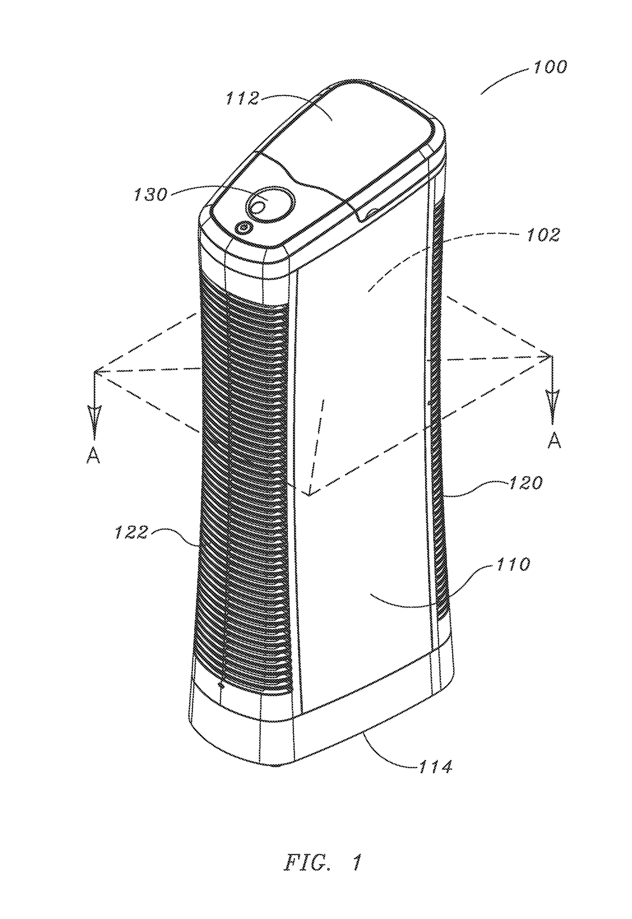
[0027]FIG. 1 is a front perspective view of an exemplary embodiment of improved electrostatic precipitation air cleaner 100. Air cleaner 100 includes housing 110 having air intake 120 and air exit 122. Housing 110 defines internal space 102. Also shown is base 114 that provides an interface between air cleaner 100 and a mounting surface, such as, for example, a floor or table. Control 130 and filter access door 112 are located on a top portion of housing 110 to provide easy access for the user.

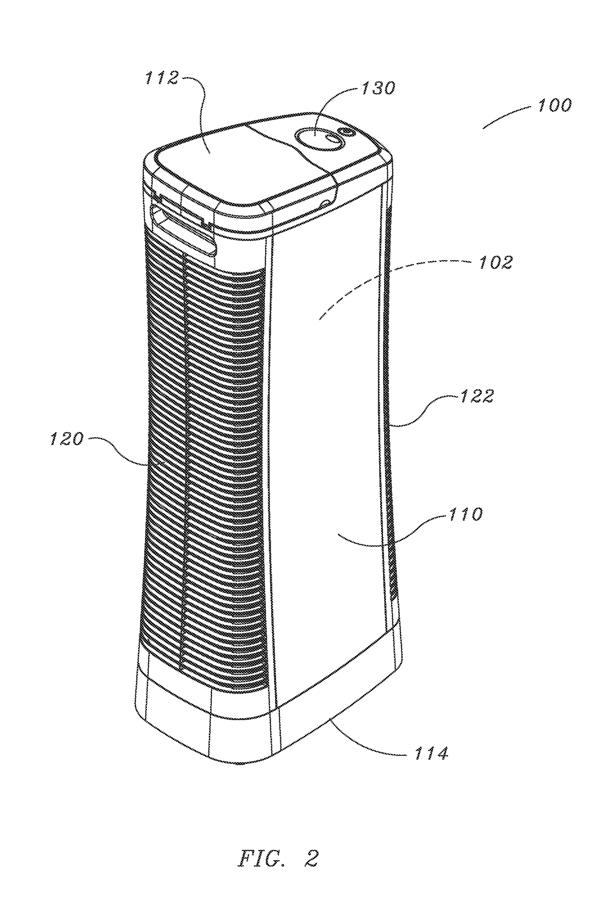
[0028]FIG. 2 is a rear perspective view of the exemplary embodiment of improved electrostatic precipitation air cleaner 100 of FIG. 1.

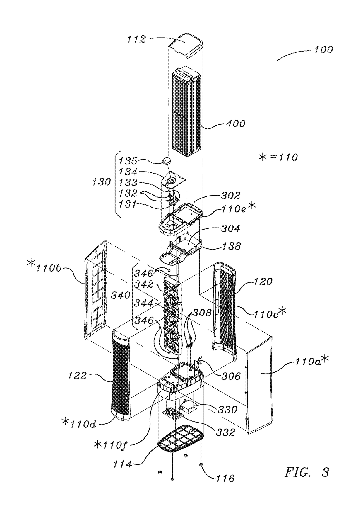
[0029]FIG. 3 is a front perspective exploded view of improved electrostatic precipitation air cleaner 100 of FIG. 1. Housing 110 is comprised of right panel 110a, left panel 110b, rear panel 110c, front panel 110d, housing top 110e, and housing bottom 110f. Air intake 120 and air exit 122 are located in rear panel 110c and front panel 110d, respectively.

[0030]Co...


PUM


Abstract

An electrostatic precipitation air cleaner to reduce ozone output is provided. The electrostatic precipitation air cleaner includes a housing with an air inlet and outlet. Located in the housing are an air mover for moving a stream of air along an airflow path between the inlet and the outlet, an ion emitter electrode positioned in the airflow path downstream of the inlet for ionizing particulates entrained in the stream of air, a collector electrode having an inlet downstream of the ion emitter electrode, and an intermediate element intermediate the ion emitter electrode and the collector electrode. The collector electrode is comprised of a plurality of collector plates spaced apart in a direction transverse to the airflow path. The plates are electrically biased to create and maintain an electric field in the space therebetween to precipitate ionized particulates entrained in the stream of air onto a confronting surfaces of the plates.

Description

RELATED APPLICATION DATA[0001]This application is a continuation of U.S. patent application Ser. No. 13 / 782,982 filed Mar. 1, 2013, which claims priority to U.S. provisional application Ser. No. 61 / 608,260 filed Mar. 8, 2012 and U.S. provisional application Ser. No. 61 / 608,274 filed Mar. 8, 2012, the contents of which are incorporated herein by reference in their entirety.TECHNOLOGY FIELD[0002]The invention is directed to the field of gas purification, and more particularly, to portable electrostatic precipitation room air cleaners utilizing multiple stage electrostatic precipitation air filtration.BACKGROUND[0003]Electrostatic precipitation room air cleaners are very effective at removing particulates from the air and particularly excel when it comes to removing small particles. The filters are cost-effective, as the user does not have to purchase replacement filters on a regular basis, and they may be reused after washing.[0004]One drawback to conventional electrostatic precipitat...

Claims


Application Information

Patent Timeline
Patent Type & Authority Patents(United States)
IPC IPC(8): B01D53/02B03C3/47B03C3/36B03C3/45B03C3/12B03C3/32B03C3/41B01D53/32
CPCB03C3/32B01D53/323B03C3/12B03C3/368B03C3/45B03C3/47B03C3/41Y02A50/2357B03C2201/04Y02A50/2351
Inventor GENEREUX, PHILIPPE J.VANDENBELT, RUDY A.
Owner LASKO OPERATION HLDG LLC
Learn More