Control of vapor emissions from gasoline stations

a technology of vapor emission and gasoline station, which is applied in the direction of filtration separation, packaging goods type, separation process, etc., can solve the problems of increasing maintenance burden, consuming additional energy for operation, and troublesome system, so as to improve vapor-liquid equilibrium and minimize vapor emission level

Active Publication Date: 2009-03-05
INGEVITY SOUTH CAROLINA
View PDF37 Cites 17 Cited by
  • Summary
  • Abstract
  • Description
  • Claims
  • Application Information

AI Technical Summary

Benefits of technology

[0025]The present invention relates to a vapor recovery system for gas station that is capable of controlling vapor emission to less than 0.38 lbs / 1000 gallons fuel dispensed. The system may include at least one canister containing adsorbents such as activated carbon, zeolite, activated alumina, silica, and other adsorbents for passive removal of hydrocarbon vapors in venting air. Additionally, the system may include a means to enhance vapor-liquid equilibrium in the ullage of the fuel tank and accordingly minimize vapor emission level.

Problems solved by technology

The pressure valve required for regulating the vacuum or pressure within the tank renders the system troublesome.
The requirement of vaccum pump in such vapor recovery systems consumes additional energy for operation and increases burden in maintenance.
The separate gaseous flow conditioning apparatus requires additional capital and installation cost.

Method used


Image

  • Control of vapor emissions from gasoline stations
  • Control of vapor emissions from gasoline stations
  • Control of vapor emissions from gasoline stations

Examples


Embodiment Construction

[0040]The present inventions now will be described more fully hereinafter, but not all embodiments of the invention are shown. Indeed, these inventions may be embodied in many different forms and should not be construed as limited to the embodiments set forth herein; rather, these embodiments are provided so that this disclosure will satisfy applicable legal requirements.

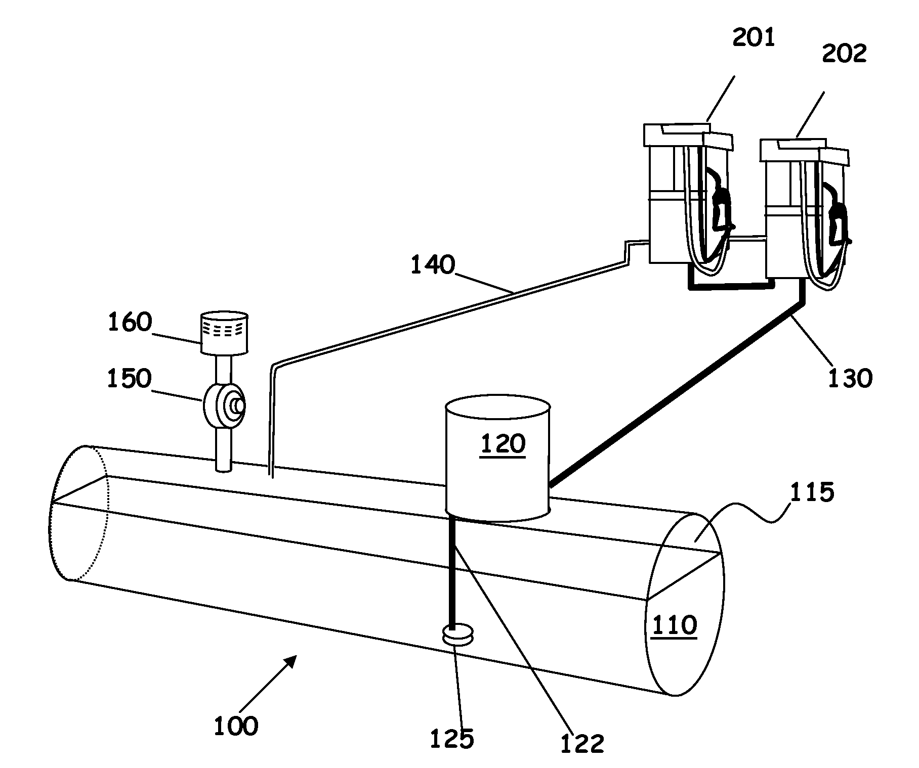
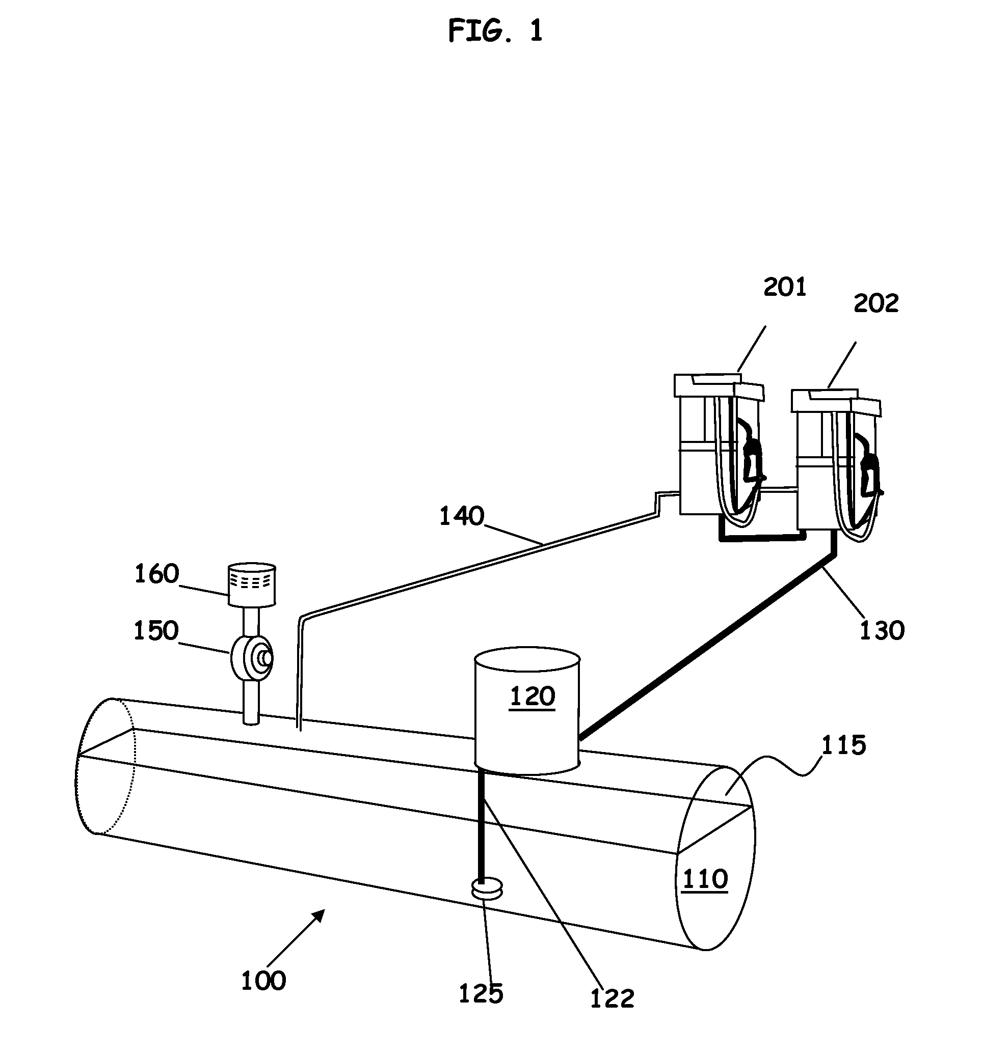
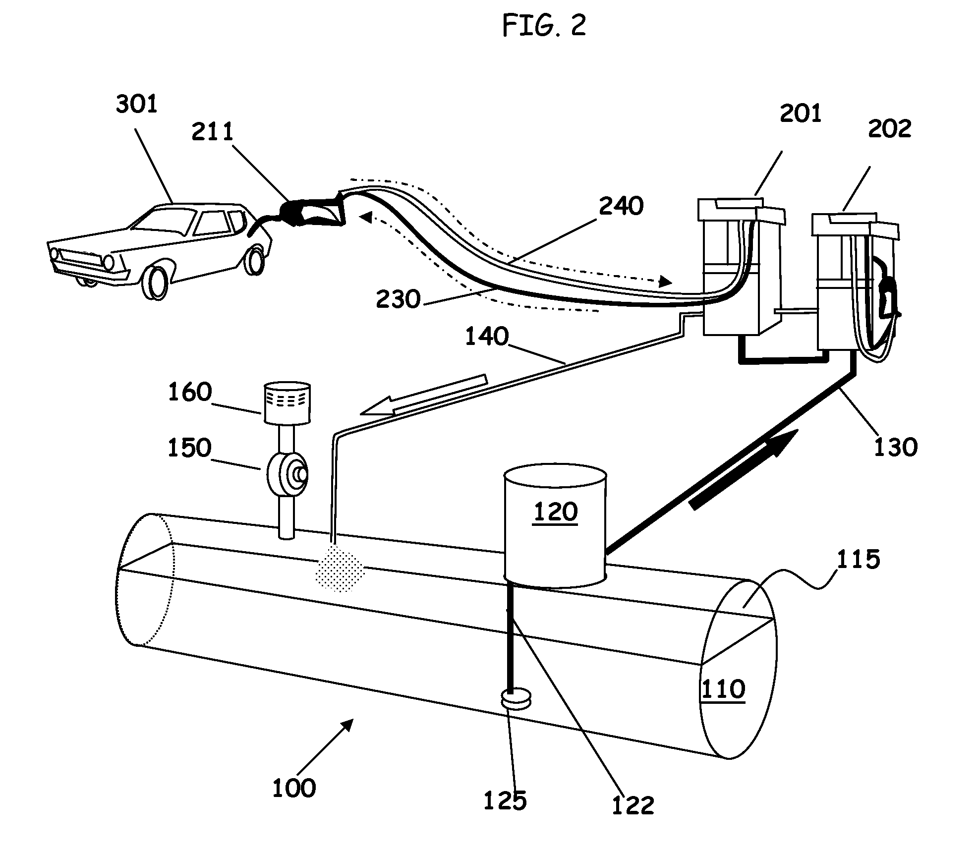
[0041]The balanced EVR system of the present invention includes at least one canister containing adsorbents to control hydrocarbon emissions from tank 100. FIG. 5 shows a cross section of a canister 400 comprises a metal or plastic housing containing an adsorbent. The design is an example and not meant to be limiting. Here the canister 400 is cylindrical, with longitudinal wall 410, a first end 420 (here the bottom and inlet end for purposes of discussion) with inlet port 422, and a second end 425 (here the top and outlet end) with outlet port 427. Canister 400 may have a volume of 4-20 gallons or larger. Additional...


PUM

PropertyMeasurementUnit
densityaaaaaaaaaa
densityaaaaaaaaaa
densityaaaaaaaaaa

Abstract

The present invention relates to a vapor recovery system for gas station that is capable of controlling vapor emission to less than 0.38 lbs / 1000 gallons fuel dispensed. The system may include at least one canister containing adsorbents such as activated carbon, zeolite, activated alumina, silica, and other adsorbents for passive removal of hydrocarbon vapors in venting air. Additionally, the system may include a means to enhance vapor-liquid equilibrium in the ullage of the fuel tank and accordingly minimize vapor emission level.

Description

[0001]This non-provisional application relies on the filing date of provisional U.S. Application Ser. Nos. 60 / 744,543 filed on Apr. 10, 2006; 60 / 744,615 filed on Apr. 11, 2006; and 60 / 862,536 filed on Oct. 23, 2006, which are incorporated herein by reference, having been filed within twelve (12) months thereof, and priority thereto is claimed under 35 USC § 1.19(e).BACKGROUND OF THE INVENTION[0002]Activated carbon has been used for removal of impurities and recovery of useful substances from liquids and gases because of its high adsorptive capacity. Generally, “activation” refers to any of the various processes by which the pore structure is enhanced. Typical commercial activated carbon products exhibit a surface area (as measured by nitrogen adsorption as used in the B.E.T. model) of at least 300 m2 / g. Common carbon sources include as resin wastes, coal, coal coke, petroleum coke, lignite, polymeric materials, and lignocellulosic materials including pulp and paper, residues from pu...

Claims


Application Information

Patent Timeline
Patent Type & Authority Applications(United States)
IPC IPC(8): B65B31/02B01D27/10B67D5/63B67D7/82
CPCB01D53/0415B01D53/0454B01D2253/102B01D2253/104B01D2259/4516B01D2253/3425B01D2257/702B01D2259/40081B01D2259/40086B01D2253/108
Inventor TSCHANTZ, MICHAEL F.
Owner INGEVITY SOUTH CAROLINA
Why Eureka
Try Eureka