Camera module lens cap

a technology for lens caps and camera modules, applied in camera filters, television systems, instruments, etc., can solve the problems of affecting the correct focusing of camera modules, etc., to achieve the effect of reducing the form factor and robust operation

Inactive Publication Date: 2009-03-05
STMICROELECTRONICS (RES & DEV) LTD +2
View PDF10 Cites 62 Cited by
  • Summary
  • Abstract
  • Description
  • Claims
  • Application Information

AI Technical Summary

Benefits of technology

[0006]In view of the foregoing background, an object of the present invention is to provide a lens cap for a camera module of a solid state image sensor with a reduced form factor without compromising on the effective packaging of components to ensure robust operation.

Problems solved by technology

If the lens is exposed it can be scratched, and if the barrel 12 is exposed, any forces applied to it can make it move and interfere with the correct focusing of the camera module.
However, with the abovementioned pressures on form factor and for other manufacturing reasons, some manufacturers prefer to omit this cover and leave the module exposed.
However, this method of protection presents a number of practical disadvantages.
Glue and adhesive tend to be more susceptible to environmental conditioning, and do not perform well in drop tests.
Furthermore, circular glass is relatively expensive compared to regular shapes such as squares or rectangles.
This is due to the extra steps required to grind the edges, and to the material that is wasted in its manufacture.

Method used


Image

  • Camera module lens cap
  • Camera module lens cap
  • Camera module lens cap

Examples


first embodiment

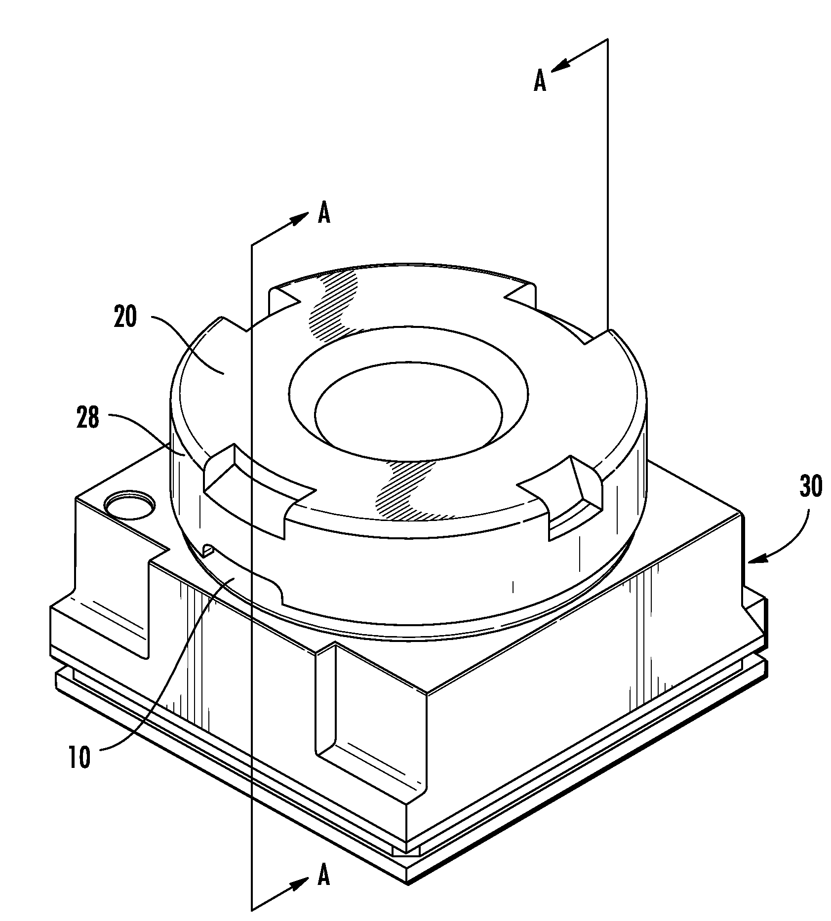
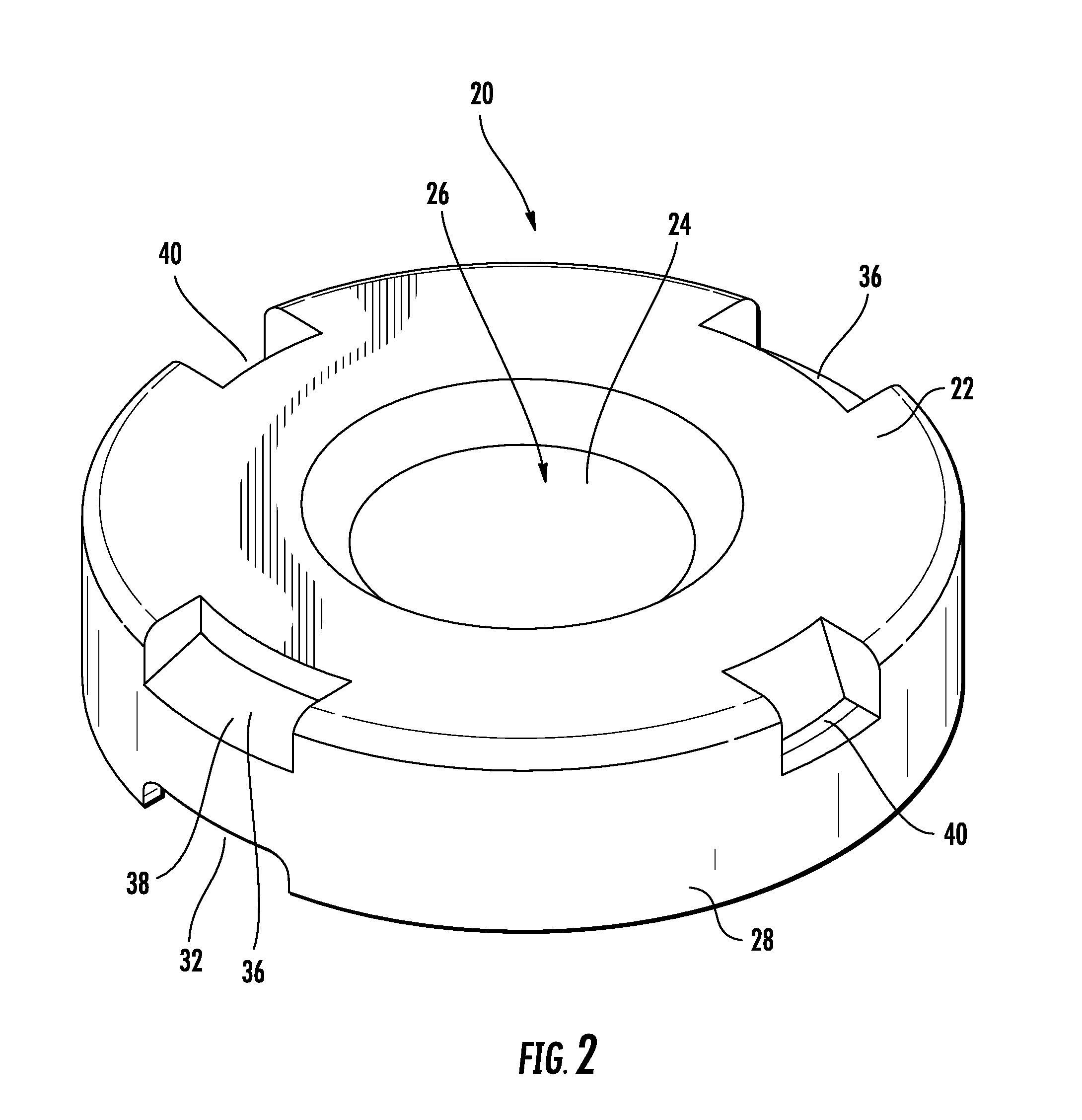
[0025]a lens cap is illustrated with reference to FIGS. 2 to 8. As shown in FIG. 2, the lens cap 20 comprises a housing 22 and an optically transparent member 24. The housing 22 comprises a one piece plastic molding formed from a material such as a liquid crystalline polymer (LCP), and includes an aperture 26 for the transmission of light. The housing 22 further comprises an overhanging lip portion 28.

[0026]As can be more clearly shown in FIG. 3, the optically transparent portion 24 comprises a square piece of optically transparent material, such as an appropriate glass or plastics material. The material is optionally coated with an anti-reflection coating on one or both sides for reducing the incidence of reflections in the images output by the image sensor. FIG. 3 shows how the square piece 24 is glued into place in the housing 22.

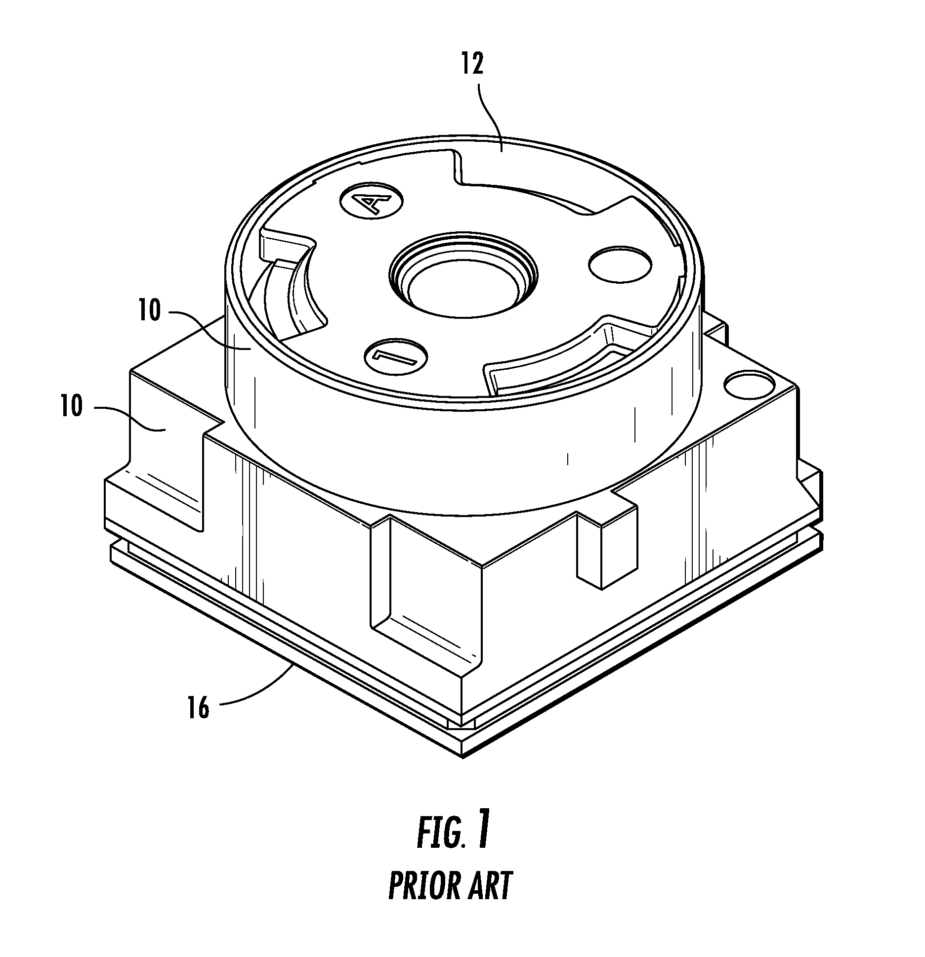
[0027]The lens cap 20 then covers a camera module 30 as shown in FIG. 4. The overhanging lip portion 28 is fixed or attached to the mount 10. This cause...

second embodiment

[0033]A lens cap is shown in FIG. 9. Instead of a two piece plastic housing with glass insert, the cap 42 can be formed from a single piece of molded material, suitably a plastics material. Typically, an optically transparent plastic will be used, and then a portion will be rendered opaque by being painted or textured, leaving an optically transparent section 44 in a central portion. The optically transparent section 44 can then be coated with an anti-reflection coating, and can also be toughened to give it glass-like properties.

[0034]It will be apparent that the cap 42 of the second embodiment shares the same advantages of the cap 20 of the first embodiment. These are directly transferable and so will not be described in detail herein.

[0035]It is to be appreciated that the lens cap could be applied to any camera module, whether or not the module would actually be exposed without the cap, and irrespective of the type of device in which it is used. That is, it is not restricted for ...


PUM


Abstract

A camera module lens cap is provided to protect a camera module in a mobile device where the camera module is exposed. The camera module lens cap includes an optically transparent member for positioning adjacent a camera lens, and a housing for carrying the optically transparent member. The housing includes an overhanging lip for engaging a base of the camera module.

Description

FIELD OF THE INVENTION [0001]The present invention relates to a camera module lens cap, and in particular, to a lens cap for a camera module of a solid state image sensor.BACKGROUND OF THE INVENTION [0002]The field of solid state image sensors is well established. CCD and CMOS sensors are found in a large number of devices from digital still cameras to mobile telephones, as well as in laptops, webcams, pointing devices and barcode readers to name but a few. Mobile devices include, but are not limited to, mobile telephones, smart phones, palmtops and personal digital assistants, for example.[0003]A typical camera module for a solid state image sensor is shown in FIG. 1. It includes a base 10, which can also be called a mount, and a barrel 12. In this example, the base 10 has a lower pedestal portion and an upper cylindrical portion which encases the barrel 12. A lens (not shown) is housed within the barrel 12, and the barrel moves vertically to adjust the focus. The lens 14 focuses i...

Claims


Application Information

Patent Timeline
Patent Type & Authority Applications(United States)
IPC IPC(8): G03B17/02
CPCH04N5/2257G03B11/00H04N23/57
Inventor BRODIE, STUARTMCINNES, HAZELLOO, KUM WENGMIGLIETTI, MICKAELSAUGIER, ERIC
Owner STMICROELECTRONICS (RES & DEV) LTD
Why Eureka
Try Eureka