Touch panel

Active Publication Date: 2009-03-05
AU OPTRONICS CORP
View PDF22 Cites 42 Cited by
  • Summary
  • Abstract
  • Description
  • Claims
  • Application Information

AI Technical Summary

Benefits of technology

[0008]It is therefore a primary objective of the present invention to provide a

Problems solved by technology

A multi-touch input is not allowable, which restric

Method used


Image

  • Touch panel
  • Touch panel
  • Touch panel

Examples


Example

[0022]Hereinafter, preferred embodiments of the present invention will be described with reference to the accompanying drawings, in which components with substantially the same functions are identified by the same reference numeral for the sake of simplicity. It should be noted, however, that the present invention is in no way limited to the following illustrative embodiments.

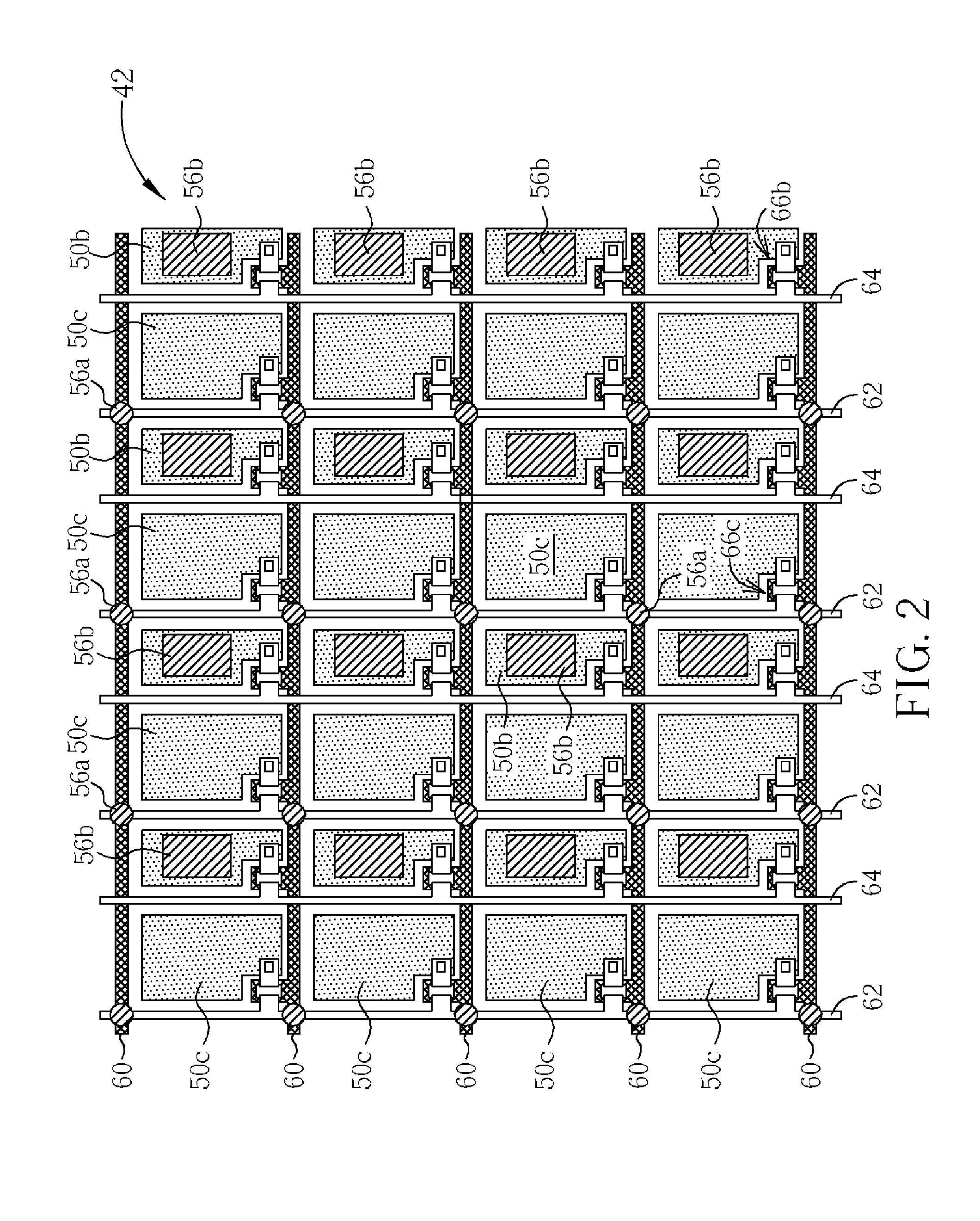
[0023]Please refer to FIG. 2 and FIG. 3, which are schematic diagrams illustrating a touch panel according to a preferred embodiment of the present invention. This embodiment takes a touch liquid crystal panel as an example, but other devices having a touch panel therein are allowable. The touch panel may work independently or be incorporated into other types of display panels. In order to emphasize the characteristics of the present invention, FIG. 2 only shows partial components of the touch panel from the top view, and FIG. 3 shows the cross-section of the touch panel. Referring to FIG. 2 and FIG. 3, the tou...


PUM


Abstract

A touch panel has a first substrate and a second substrate. The thickness in the non-sensor regions of the first substrate is greater than the thickness in the sensor regions of the first substrate. The second substrate includes first photo spacers and second photo spacers having substantially the same heights. The first photo spacers are structurally connected to the non-sensor regions of the first region of the first substrate, and the second photo spacers are positioned corresponding to the sensor regions of the first substrate that maintain a first gap with the first substrate.

Description

BACKGROUND OF THE INVENTION[0001]1. Field of the Invention[0002]The present invention is related to a touch panel, and particularly, to a touch liquid crystal display panel.[0003]2. Description of the Prior Art[0004]Portable electronic devices such as PDAs, mobile phones, global positioning systems (GPS), and digital video players generally use a touch panel as the communicating interface between a user and the machine. Modern consumer electronic devices are increasingly smaller and lighter. In order to save space, a touch panel, which inputs data when it is touched, is the key component of modern consumer electronic devices, replacing traditional input devices, such as keyboards and mouse.[0005]Please refer to FIG. 1, which is a schematic diagram showing a conventional touch panel. The conventional touch panel 10 is placed on a display side of a display panel 30. The touch panel 10 has a conductive glass substrate 12, a conductive thin film 14 disposed on the conductive glass subst...

Claims


Application Information

Patent Timeline
IPC IPC(8): G06F3/041
CPCG06F3/0412G06F3/047G06F3/0447
Inventor LEE, HSIN-HUNGLIU, PO-YUANLIN, CHING-HUANCHIANG, MIN-FENGMA, MEI-SHENG
Owner AU OPTRONICS CORP
Why Eureka
Try Eureka