Electronic Camera

Inactive Publication Date: 2009-03-05
XACTI CORP
View PDF15 Cites 18 Cited by
  • Summary
  • Abstract
  • Description
  • Claims
  • Application Information

AI Technical Summary

Benefits of technology

[0013]Further preferably, the integrator individually integrates a plurality of high-frequency components respectively corresponding to a plurality of areas allocated on the imaging surface, and the adjustor further includes a designator for sequentially designating each of the

Problems solved by technology

Thereby, it becomes probable that a focus adjusting operation becomes unstable.
As a result, the focusing control may be impossible.
In contrary, when the above-described reference value is set high, it is not possible to exclude a block to which a high-luminance blurred image on a periphery of the light source belongs, and thus, there is a probability that the focusing control fails.

Method used


Image

  • Electronic Camera
  • Electronic Camera
  • Electronic Camera

Examples


Embodiment Construction

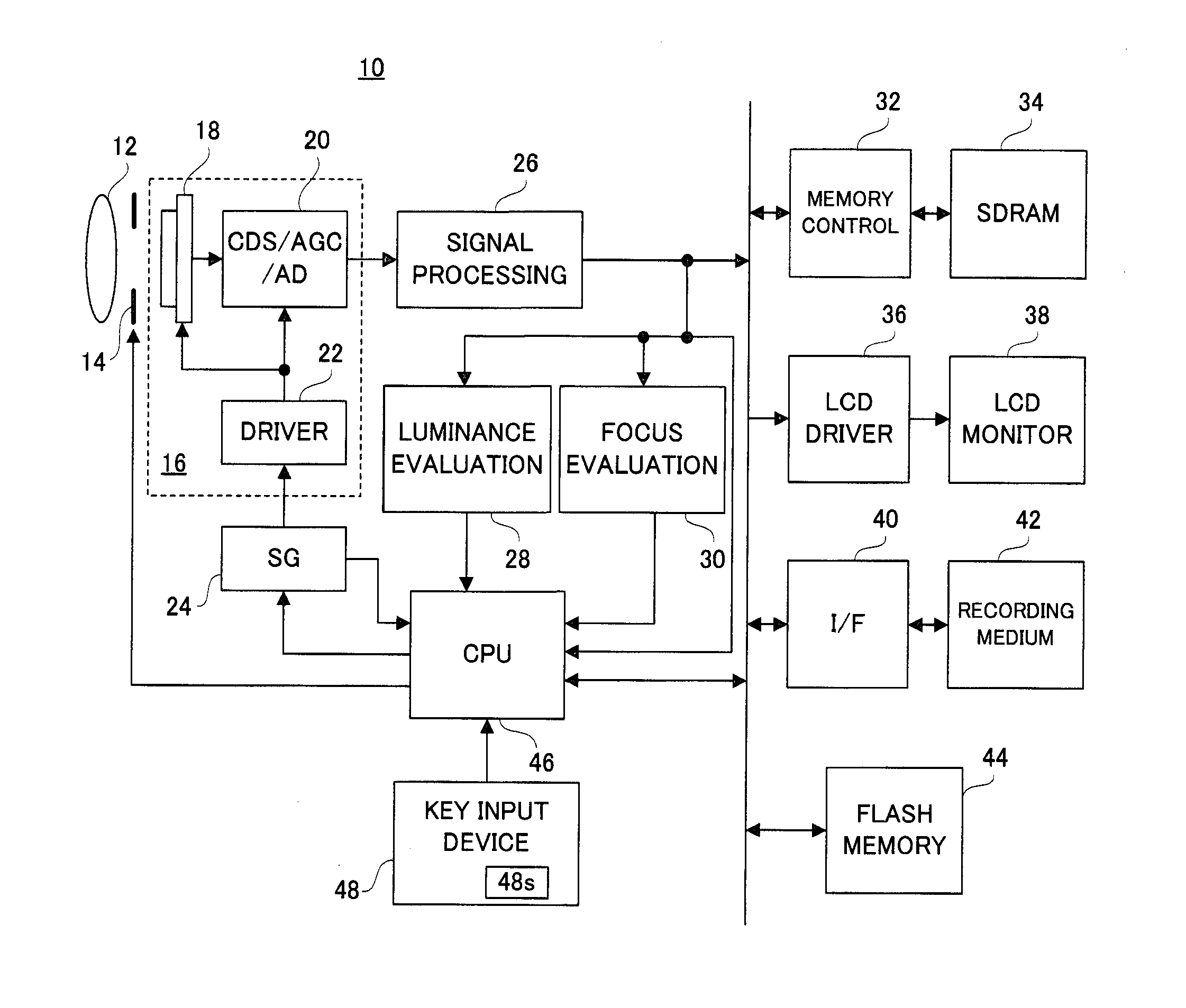
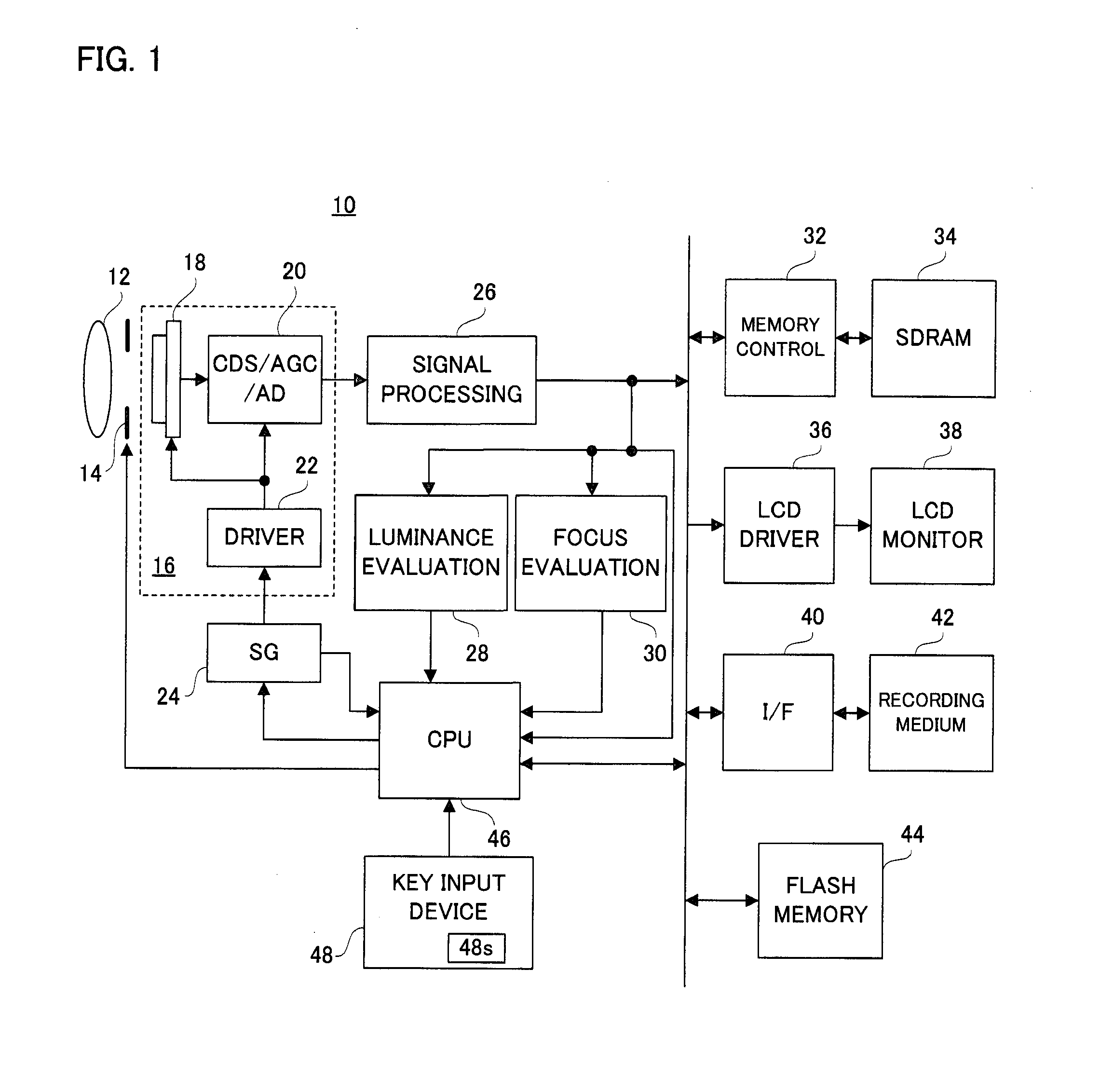
[0056]With reference to FIG. 1, a digital camera 10 according to this embodiment includes a focus lens 12 and an aperture unit 14. An optical image of an object scene through these members is irradiated onto a front surface, i.e., an imaging surface of an imaging portion 18 configuring a CMOS-type image sensor 16, and is then photoelectrically converted. Thereby, a raw image signal formed of electric charges representing an object scene image is generated.

[0057]When a power source is turned on, a through-image process is executed. A CPU 46 instructs a driver 22 configuring the image sensor 16 to repeat pre-exposure operations and thin-out reading operations. The driver 22 exposes the imaging surface at each time a vertical synchronization signal Vsync is outputted from an SG (Signal Generator) 24, and reads out a part of the electric charges thus generated from the imaging portion 18 in a raster scanning mode. The vertical synchronization signal Vsync is outputted from the SG 24 at ...


PUM


Abstract

An electronic camera includes an image sensor. The image sensor has an imaging surface irradiated with an optical image of an object scene through a focus lens and repeatedly generates an object scene image. A CPU executes an AF process for adjusting a distance from the focus lens to the imaging surface to a distance corresponding to a focal point, based on the object scene image generated by the image sensor. However, the CPU has a high-luminance excluding function for excluding from a target to be noticed of the AF process a partial image having a luminance exceeding “TH1” out of the object scene image generated by the image sensor. The CPU determines whether or not a partial image having a luminance exceeding “TH2” larger than “TH1” exists on the object scene image generated by the image sensor, and turns on the high-luminance excluding function when a determination result is affirmative and turns off the high-luminance excluding function when the determination result is negative.

Description

CROSS REFERENCE OF RELATED APPLICATION[0001]The disclosure of Japanese Patent Application Nos. 2007-219874 and 2007-220121 which were filed on Aug. 27, 2007 is incorporated herein by reference.BACKGROUND OF THE INVENTION[0002]1. Field of the Invention[0003]The present invention relates to an electronic camera. More specifically, the present invention relates to an electronic camera that references an object scene image generated on an imaging surface to adjust a distance from an optical lens to the imaging surface.[0004]2. Description of the Related Art[0005]According to one example of this type of camera, a plurality of focus evaluation values respectively corresponding to a plurality of blocks on an imaging surface are obtained by each lens position. Focusing control is executed based on a focus evaluation value, out of the plurality of focus evaluation values thus obtained, corresponding to a block different from a block to which a low-contrast image or a high-luminance image bel...

Claims


Application Information

Patent Timeline
IPC IPC(8): H04N5/228H04N5/225
CPCH04N5/23212H04N23/673
Inventor TSUJINO, KAZUHIROMIZUGUCHI, DAISUKE
Owner XACTI CORP
Why Eureka
Try Eureka