Magnification Controlling System Used In An Image Forming Apparatus
- Summary
- Abstract
- Description
- Claims
- Application Information
AI Technical Summary
Benefits of technology
Problems solved by technology
Method used
Image

Examples
first embodiment
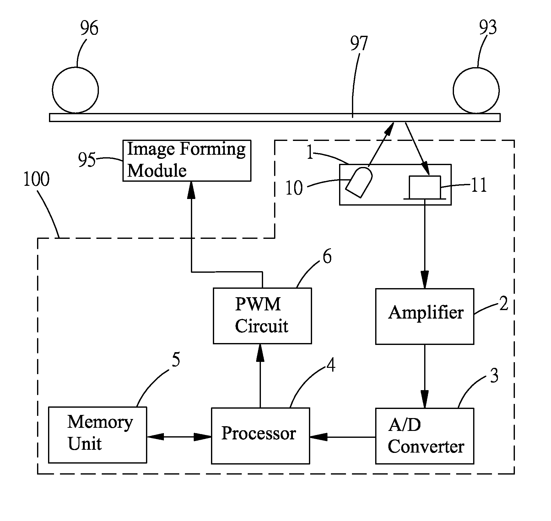
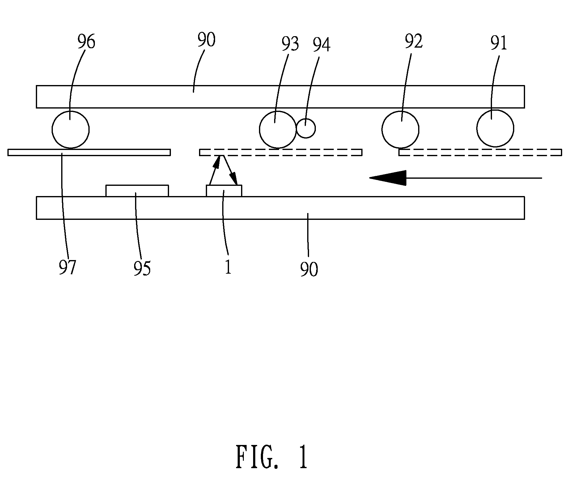
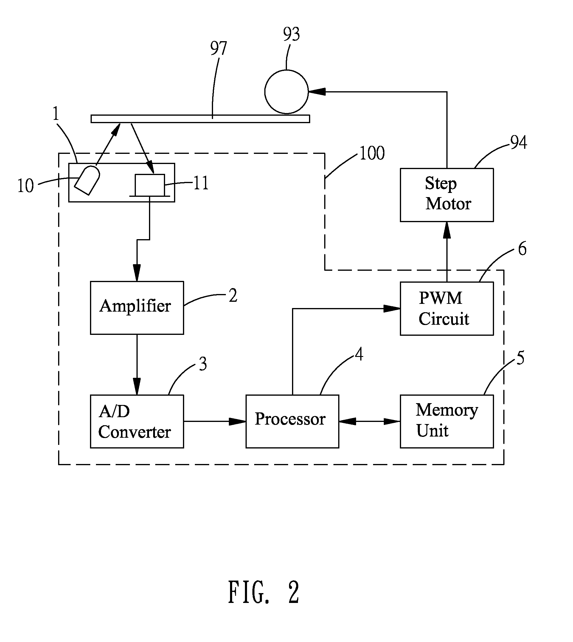
[0045]Please refer to FIG, 2 again. In the magnification controlling system 100, the PWM circuit 6 connects the step motor 94 which connects the feeding roller 93. The PWM circuit 6 sends the PWM signal to the step motor 94 for controlling rotation speed of the step motor 94. Therefore, conveying speed of the feeding roller 93 is corresponding to rotation speed of the step motor 94 which is controlled by the PWM signal produced by the PWM circuit 6.
[0046]Please refer to FIG. 4a, FIG. 4b and FIG. 4c. FIG. 4a, FIG. 4b and FIG. 4c show digital images which are read by the sensor module 1 and converted by the A / D converter 3 when the feeding roller 93 rotating in predetermined speed. The digital image shown in FIG. 4a and the digital image shown in FIG. 4b is between an interval time. The digital image shown in FIG. 4b and the digital image shown in FIG. 4c is also between the interval time.
[0047]Please refer to FIG. 5. In this case, the trigger signal has several pulses for triggering ...
second embodiment
[0064]Please refer to FIG, 8. In the magnification controlling system 100, the PWM circuit 6 connects the image forming module 95. The PWM circuit 6 sends the PWM signal to the image forming module 95 for controlling scanning speed of the image forming module 95.
[0065]Please refer to FIG. 4a, FIG. 4b, FIG. 4c and FIG. 9. In this case, the trigger signal has several pulses for triggering the sensor module 1 to read the image from predetermined area of the documents 97. In this case, each pulse is between 3 millisecond (ms). Therefore, the sensor module 1 reads the image from the predetermined area of the documents 97 once every 3 ms.
[0066]In this case, the predetermined speed vale is 0.6 millimeter / ms (mm / ms) which is stored in the memory unit 5. The PWM circuit 6 produces a predetermined PWM signal and sends the predetermined PWM signal to the image forming module 95. In this case, the predetermined PWM signal has several pulses. Each pulse of the predetermined PWM signal is between...
PUM
 Abstract
Description
Claims
Application Information
 - Generate Ideas
- Intellectual Property
- Life Sciences
- Materials
- Tech Scout
- Unparalleled Data Quality
- Higher Quality Content
- 60% Fewer Hallucinations
Browse by: Latest US Patents, China's latest patents, Technical Efficacy Thesaurus, Application Domain, Technology Topic, Popular Technical Reports.
© 2025 PatSnap. All rights reserved.Legal|Privacy policy|Modern Slavery Act Transparency Statement|Sitemap|About US| Contact US: help@patsnap.com