Method and apparatus for transmitting and receiving packets in a mobile communication system

Active Publication Date: 2009-03-05
SAMSUNG ELECTRONICS CO LTD
View PDF10 Cites 13 Cited by
  • Summary
  • Abstract
  • Description
  • Claims
  • Application Information

AI Technical Summary

Benefits of technology

[0013]Accordingly, the present invention has been designed to address at least the problems and/or disadvantages and to provide at least the advantages described below. Accordingly, an aspect o

Problems solved by technology

However, this is inefficient for the service in which a packet of several tens of byt

Method used


Image

  • Method and apparatus for transmitting and receiving packets in a mobile communication system
  • Method and apparatus for transmitting and receiving packets in a mobile communication system
  • Method and apparatus for transmitting and receiving packets in a mobile communication system

Examples


first embodiment

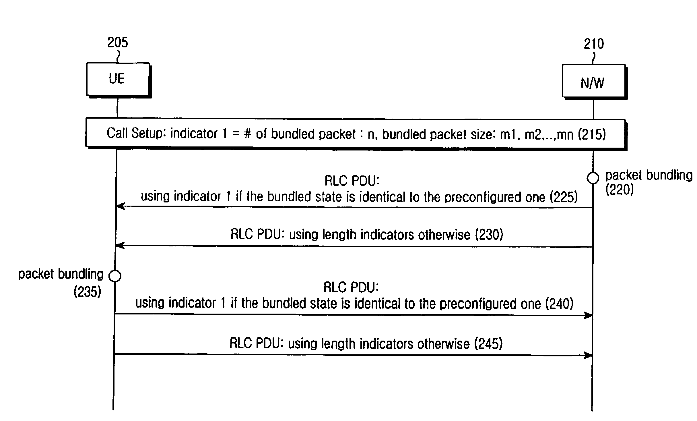
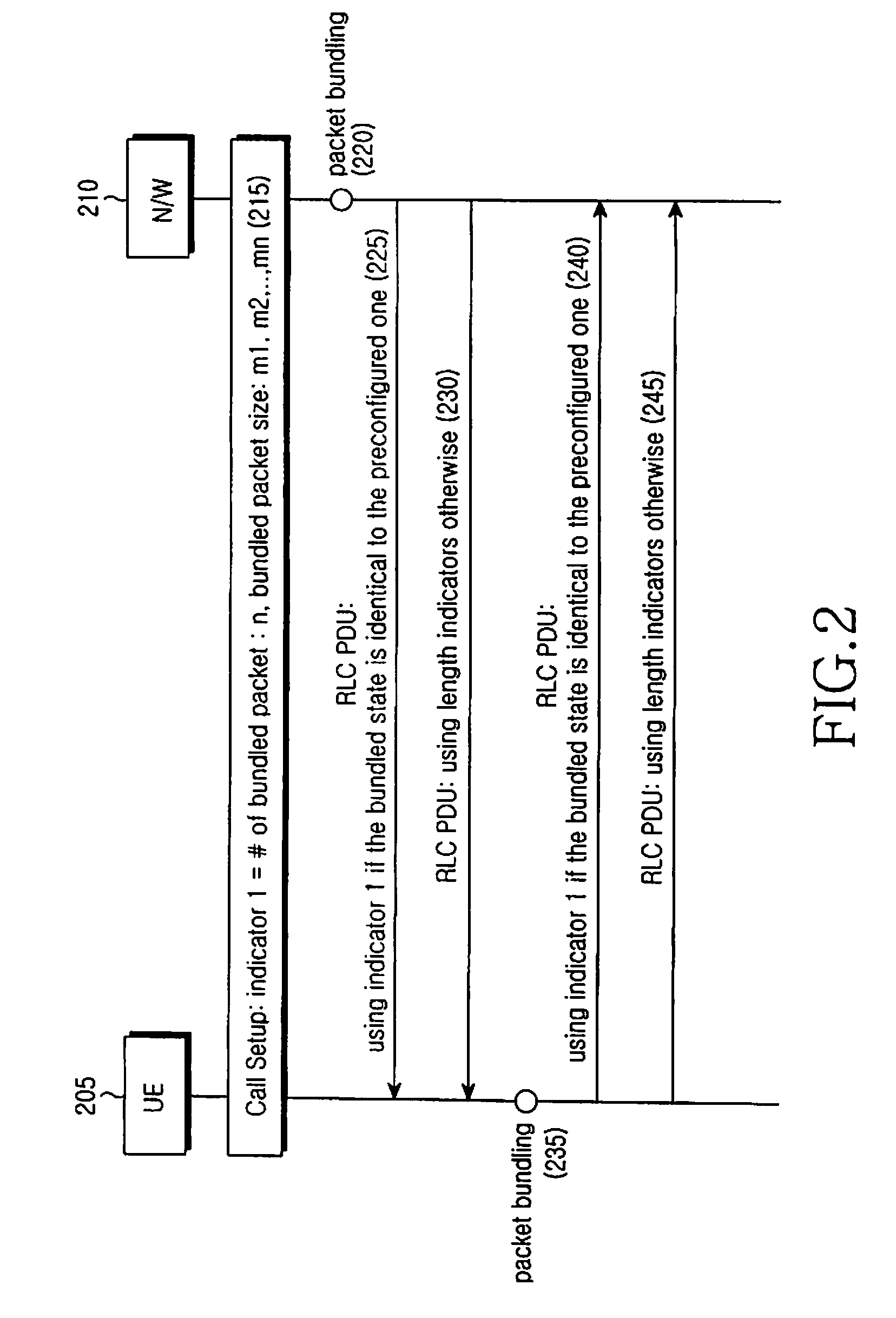
[0035]For convenience, an operation of simultaneously including several SDUs in one PDU will be referred to herein as “bundling”.

[0036]In a first embodiment of the present invention, in setting up an arbitrary call, a network determines whether to perform bundling based on a property of the call. If the network has determined to bundle SDUs of an arbitrary call, the network determines the number of SDUs that should undergo bundling, based on the transmission delay requirement of the corresponding call. The network determines the number of bundled SDUs to be indicated as a first indicator, and a size of the bundled SDUs, based on a size of the SDU that is most frequently generated in the call. The network then notifies a UE of the number of bundled SDUs indicated by the first indicator and the size of the bundled SDUs. Thereafter, if the number of SDUs bundled in one PDU coincides with a definition given by the first indicator, a transmission device indicates the bundled state of SDU...

second embodiment

[0062]The second embodiment of the present invention proposes a method for signaling, using indicator 1, information indicating that (n−1) SDUs with a size s and the remaining one SDU, a size of which can be estimated from a size of an arbitrary PDU, are bundled in the corresponding PDU.

[0063]In transmitting and / or receiving a PDU of an arbitrary protocol layer x, a transmission side signals a size of the PDU to a reception side through a header of the next lower protocol layer of the protocol layer x or through a separate control signal. For example, a size of the RLC PDU is indicated in a MAC header, and a size of a MAC PDU is notified to the reception device by a physical layer control signal. When the surplus information indicates the size of the PDU, it is possible to use indicator 1 and more flexibly set a size of the last SDU included in the PDU. For example, the transmission device and the reception device define indicator 1 as an indicator that indicates that (n−1) SDUs wit...

third embodiment

[0079]The third embodiment of the present invention proposes a method for signaling, using indicator 1, information indicating that n SDUs with a size=m / n are contained in an arbitrary PDU. Here, m denotes a payload size of the PDU, and is a value obtained by subtracting a size of a PDU header from the total size of the PDU.

[0080]When the third embodiment of the present invention is used, once SDUs bundled in one PDU are equal in size, it is possible to use indicator 1 regardless of the actual size of the SDUs. Therefore, it is possible to increase the frequency of uses of indicator 1, resulting in a reduction in the overhead caused by length indicators.

[0081]FIG. 10 illustrates indicator 1 according to the third embodiment of the present invention. It is assumed that n SDUs 1015 with a size-m / n 1010 are contained in an RLC PDU with indicator 1=‘on’1005, and the last byte of the last SDU is identical to the last byte of the PDU payload. Here, m denotes a payload size of the PDU, and...


PUM


Abstract

A method for transmitting a packet over a radio channel in a mobile communication system. The method includes receiving first packets from an upper layer; checking a number of and a size of the first packets to be bundled in a second packet; generating the second packet using the first packets and a header including an indicator that indicates if the number of and a size of the first packets to be bundled in the second packet satisfy a predetermined condition; and transmitting the generated second packet via a lower layer.

Description

PRIORITY[0001]This application claims priority under 35 U.S.C. § 119(a) of a Korean Patent Application filed in the Korean Intellectual Property Office on Apr. 25, 2007, and assigned Serial No. 2007-40570, the disclosure of which is incorporated herein by reference.BACKGROUND OF THE INVENTION[0002]1. Field of the Invention[0003]The present invention relates generally to a method and apparatus for transmitting and receiving packets in a mobile communication system, and in particular, to a method and apparatus including several upper layer packets in one lower layer packet before transmission in order to reduce header overhead[0004]2. Description of the Related Art[0005]In the next generation mobile communication systems, a base station schedules data transmission / reception in real time. For example, a terminal or User Equipment (UE) reports the data generation and channel condition to a base station (Step 1). The base station identifies a UE that will transmit data in the next transm...

Claims


Application Information

Patent Timeline
IPC IPC(8): H04W16/00
CPCH04W28/06H04L47/10H04W80/02
Inventor KIM, SOENG-HUNVAN LIESHOUT, GERT JAN
Owner SAMSUNG ELECTRONICS CO LTD
Why Eureka
Try Eureka