Portable device with heat radiating structure

Inactive Publication Date: 2009-03-05
XACTI CORP
View PDF6 Cites 5 Cited by
  • Summary
  • Abstract
  • Description
  • Claims
  • Application Information

AI Technical Summary

Benefits of technology

[0012]The heat from the heat generating body flows and spreads not only to the connection member but also to the other end of the cabinet through the radiati

Problems solved by technology

Thus, during use, the fingers of the user merely touch the cover strip, and heat transmitted from the heat generating bod

Method used


Image

  • Portable device with heat radiating structure
  • Portable device with heat radiating structure
  • Portable device with heat radiating structure

Examples


Example

[0020]One example of the present invention will be described using the drawings.

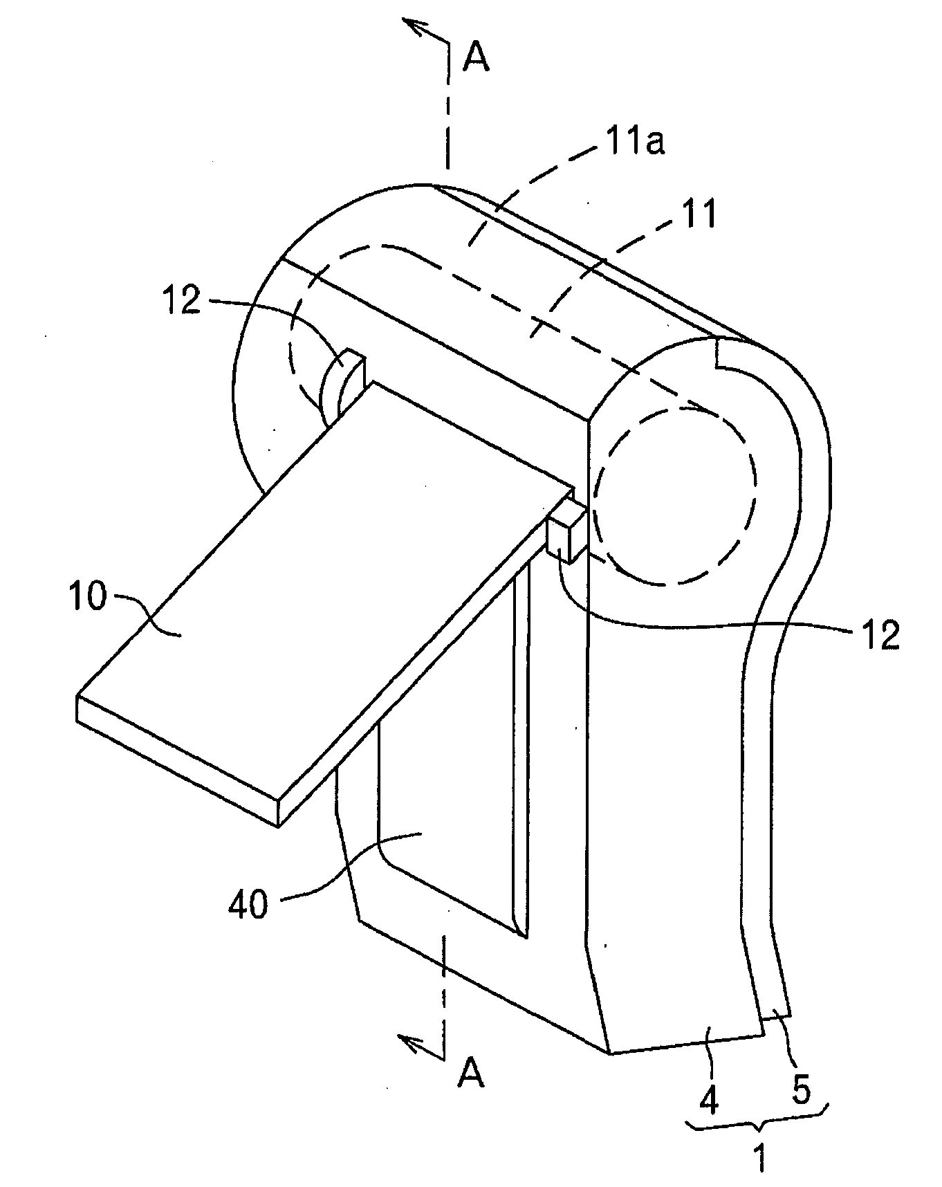
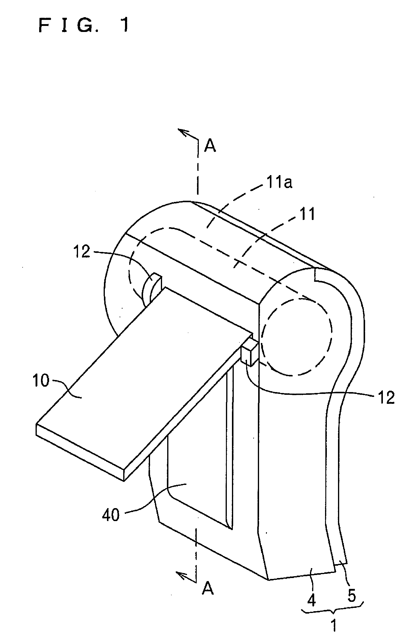
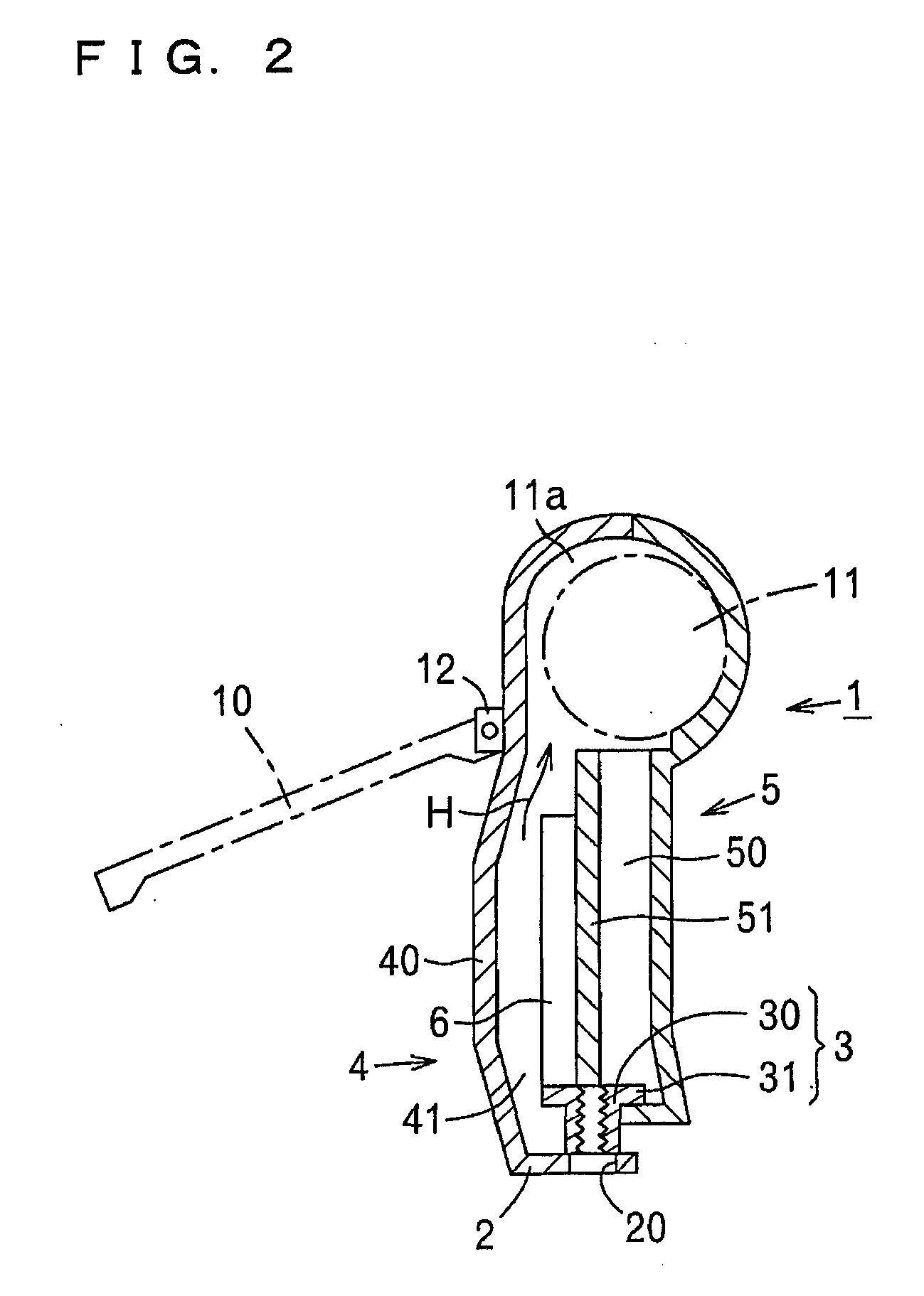
[0021]FIG. 1 is a perspective view of a camera equipment related to the present example, more specifically, a digital camera; and FIG. 2 is a view taken along a vertical plane including line A-A of FIG. 1. A cabinet (1) is configured by horizontally overlapping a first cabinet half-body (4) and a second cabinet half-body (5), which are both made of synthetic resin, where a lens barrel (11) is accommodated in a space (11a) formed at an upper end of the half-bodies (4), (5). A display plate (10), which is a liquid crystal panel, is arranged on the exterior of the first cabinet half-body (4) so as to be pivotable upward and downward, a basal end of which display plate (10) being pivotally supported by bearings (12), (12) arranged at the upper end of the first cabinet half-body (4). A projection (40) is formed on the first cabinet half-body (4) at an area to be covered by the display plate (10).

[0022]The dis...


PUM


Abstract

In a digital camera implementing the present invention, a metal tripod seat is arranged on a cabinet, a circuit part that generates heat is accommodated in the cabinet, the circuit part is connected with the tripod seat in a heat conducting manner, and a cover strip made of resin extending from the cabinet covers the tripod seat. The tripod seat is arranged at one end of the cabinet, and the outer surface of the cabinet has a projection formed at a site facing the circuit part, and forms a heat radiating space allowing flow of heat to the other end of the cabinet with the circuit part.

Description

CROSS REFERENCE OF RELATED APPLICATION[0001]This application claims priority from Japanese Patent Application 2007-219209 filed on Aug. 27, 2007.BACKGROUND OF THE INVENTION[0002]1. Field of the Invention[0003]The present invention relates to a portable device having a heat radiating structure, specifically, to a portable device such as digital camera having a structure for escaping internal heat to the outside.[0004]2. Description of the Related Art[0005]FIG. 7 is a view showing a side surface of a digital camera having a heat radiating structure of the prior art in a partially cut-out manner. As well-known, circuit parts (6) such as CCD and LSI are arranged in a cabinet (1) including a lens barrel (11). The circuit parts (6) are attached to a metal circuit holding plate (66) by way of a wiring substrate (65). A metal tripod seat (3) formed with a screw hole (32) for a tripod (not shown) is arranged at the lower surface of the cabinet (1), and the circuit holding plate (66) is conne...

Claims


Application Information

Patent Timeline
IPC IPC(8): G03B17/55
CPCG03B17/55
Inventor SASAKI, YOSHIKAZU
Owner XACTI CORP
Why Eureka
Try Eureka