Laser cutting head for machine tool

Active Publication Date: 2015-05-28
SALVAGNINI ITAL
View PDF9 Cites 4 Cited by
  • Summary
  • Abstract
  • Description
  • Claims
  • Application Information

AI Technical Summary

Benefits of technology

[0023]During the operation of the laser cutting head, the heat generated in the focusing lens by the passage of the laser beam is transferred and surrendered by the support element and thermal conductive devices to the Peltier cell which, suitably powered and commanded by direct current, surrenders this heat to the heat dissipation element. The removal of heat by the Peltier cell, working as a heat pump, thus allows the temperature of the focusing lens to be controlled and, in particular, prevents it from overheating, which would result in a variation in its refraction index and thus an uncontrolled focal shift. The thermal efficiency of the system for coo

Problems solved by technology

The focused laser beam leaves the focusing head through a cutting nozzle which concentrates the blast or jet of gas used to remove the dross generated by the fusion of the metal and limits the probability of the dross reaching the focusing unit.
This increase in temperature causes a variation in the refraction index of the lens itself and thus a shift in the focus.
This phenomenon, commonly referred to as “thermal focus shift”, thus makes it impossible for the cutting system to focus the laser beam in the desired optimal point on the surface of the workpiece, and determines a consequent deterioration in the cutting characteristics to the

Method used


Image

  • Laser cutting head for machine tool
  • Laser cutting head for machine tool
  • Laser cutting head for machine tool

Examples


Example

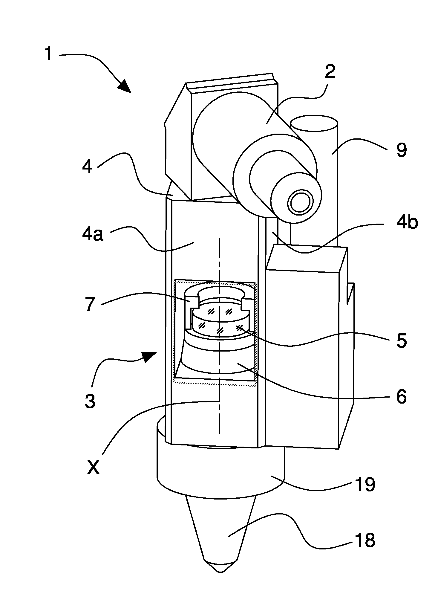
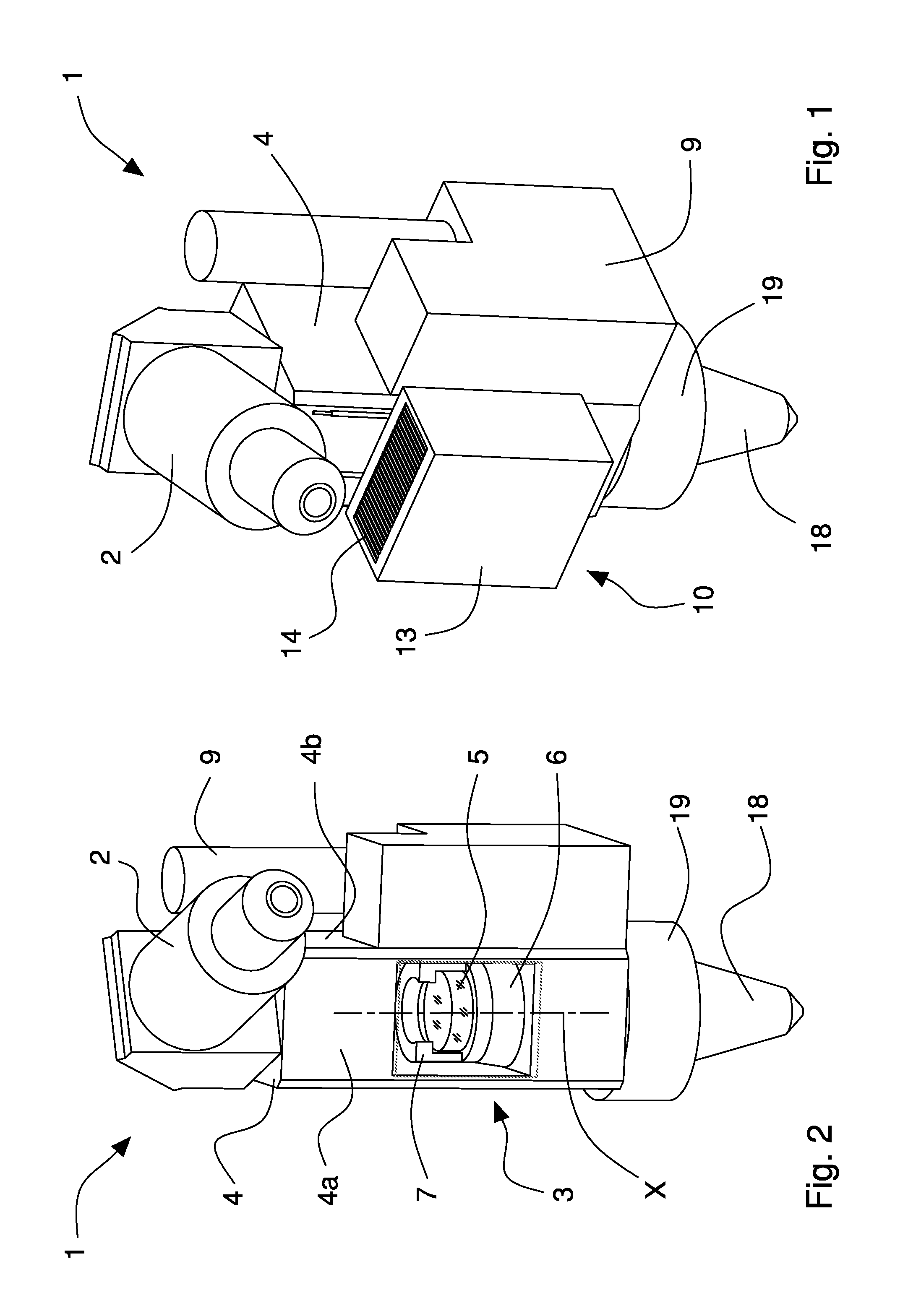
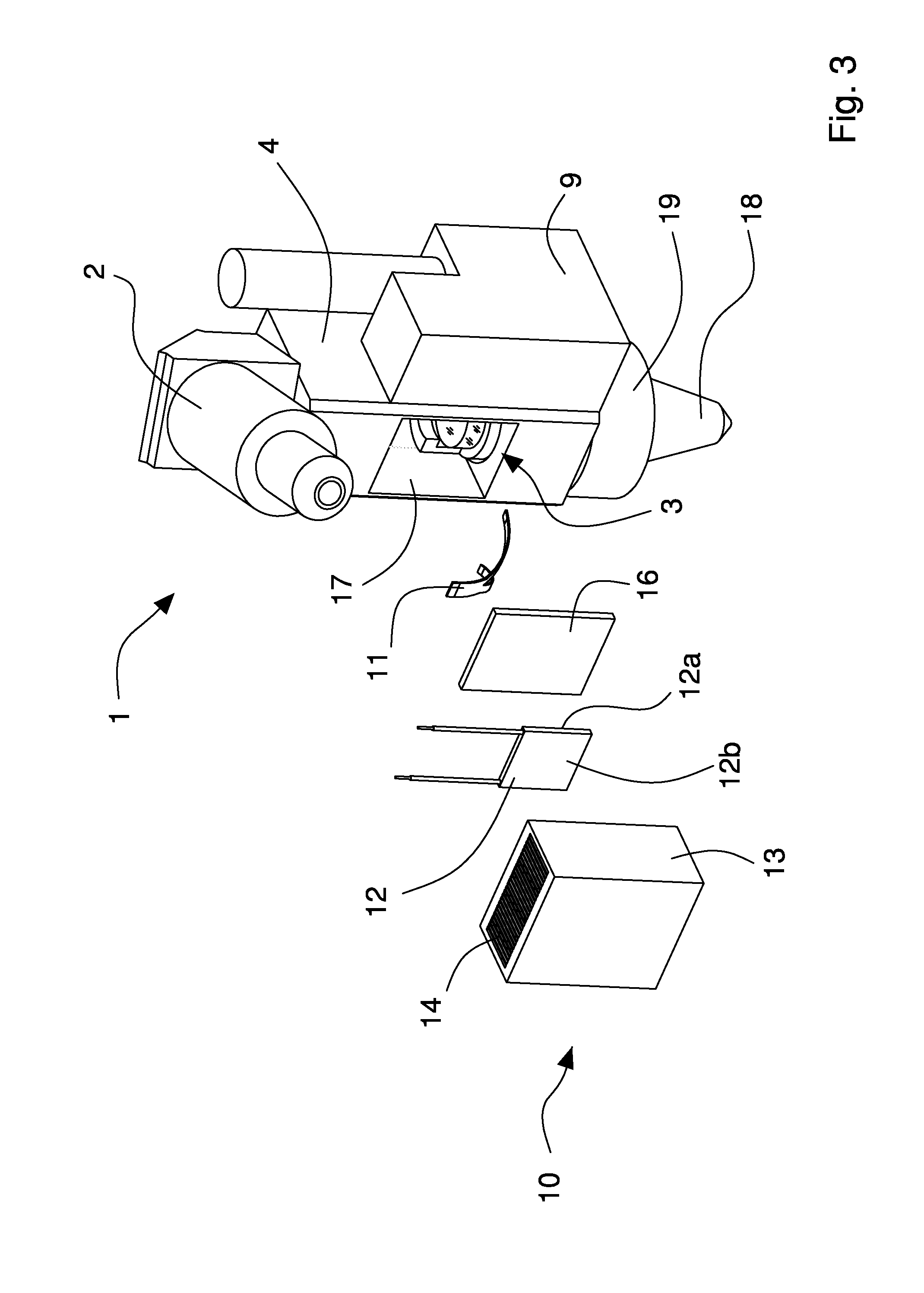
[0037]FIGS. 1 to 7 illustrate a laser cutting head 1 in accordance with the present invention, for feeding by a laser emission apparatus, of a known type not illustrated in the Figures, by means of optical transmission devices and associable with a cutting machine tool. In particular, the emission apparatus is of the solid-state laser stimulated emission type, and the optical transmission devices include an optical fiber cable capable of transporting the laser beam generated by the emission apparatus to the laser cutting head 1.

[0038]The laser cutting head 1 includes a collimation device 2 for collimating the laser beam generated by the laser emission apparatus, focusing devices 3 for focusing the collimated laser beam leaving the collimation device 2 and a casing 4 for containing and housing the focusing unit 3.

[0039]The cutting head 1 also includes a cutting nozzle 18 that is secured to the casing 4 by an optical centering ring-nut 19 and through which the focused laser beam passe...


PUM

PropertyMeasurementUnit
Flexibilityaaaaaaaaaa
Electrical conductoraaaaaaaaaa
Thermal conductivityaaaaaaaaaa

Abstract

A laser cutting head powered by a laser emission apparatus including optical transmission devices and associated with a cutting machine tool, includes collimation device to collimate a laser beam coming from the laser emission apparatus, focusing device to focus a collimated laser beam leaving the collimation devices and a casing to house and contain the focusing unit. The focusing unit includes at least one focusing lens and support devices to house and hold the focusing lens and move it along an adjustment direction within the casing in order to vary a focal point of the laser beam leaving the focusing lens. The laser cutting head includes a cooling unit secured to the casing and heat conducting devices used to connect the support devices with the cooling unit in order to extract the heat generated by the laser beam crossing the focusing lens by thermal conduction from the support devices and from the focusing lens.

Description

BACKGROUND OF THE INVENTION[0001]The present invention relates to laser cutting devices for cutting machine tools and in particular it relates to a laser cutting head to be used in a fiber optic laser cutting system in a cutting / punching machine tool for sheet metal.[0002]The use of laser systems for cutting, engraving and welding parts is well known and widely used in the sector of machine tools for processing metal sheets and plates.BRIEF DESCRIPTION OF THE PRIOR ART[0003]Lasers are known to be devices capable of emitting a coherent, monochrome beam of light, concentrated in a rectilinear radius and having extremely high luminosity (brilliance), by means of a process of stimulated emission. The possibility of concentrating a large amount of energy in a very small point enables laser devices to cut, engrave and weld metal. The cutting of metallic material typically occurs through vaporization and, in particular, through fusion, where the laser beam melts a small point of the metal ...

Claims


Application Information

Patent Timeline
IPC IPC(8): B23K26/38B23K26/30B23K26/14B23K26/06
CPCB23K26/38B23K26/1417B23K26/423B23K26/06B23K26/0665B23K26/1462B23K26/703
Inventor GESUITA, ENZOMANZO, RICCARDO
Owner SALVAGNINI ITAL
Why Eureka
Try Eureka