Automatic cooker

Inactive Publication Date: 2005-03-29
SO FUK SANG
7 Cites 4 Cited by

AI-Extracted Technical Summary

Problems solved by technology

In addition, the operator could not go away from the oven-range as well as the heat generated from the cooking process makes the kitchen room overheated and polluted, thus making the environment of the kitchen undesirable.
The traditional coo...

Method used

The automatic cooker further includes a ventilator motor 12 which is connected to the blade assembly 11 of the ventilating fan. Air inlet is at 16, 17. The air there mixes with fumes. There is an outlet for gas and fumes at 13 and 15 through which the gas and fumes are conveyed by the ventilation for 11. In order to increase the pressure of it, the gas is introduced into water where the gas and fume are filtered out. The blade assembly 11 comprises at least two sets of blades. Air outflow ports 10 are provided on the side of the lower portion of the blade assembly 11 so that the gas sucked by the blade assembly 11 is introduced into water through air outflow ports 10. A pump 23 (as shown in FIG. 5) is mounte...

Benefits of technology

In the automatic cooker according to the present invention, the cooking body is attached to the column and when the cooking body is driven with the power supply unit, the cooking body rotates in latitudinal direction so that the food to cook in the cooking body will be stirred up continuously. Particularly, the stirring rib provided in the cooking body enhances the stirring effect of the food (both solid food and liquid food). With this configuration, the present invention provides an automatic cooker which may partly or wholly replace the manual operation of stirring the food being cooked. Provided with timing device, signal device and alarming device in the power supply unit, the automatic cooker can heat the food being cooked evenly and prevent it from overheated in case that the operator is away from the range-oven. In addition, various cooking operation such as frying, stir-frying, steaming, braising and stewing can be performed by adjustment the rotation ang...

Abstract

The invention relates to a cooking utensil, and more particularly, to an electric automatic cooker. The automatic cooker includes semi-spherical cooking body which is driven with a power motor to rotate in both longitudinal direction and latitudinal direction. The automatic cooker further includes a stirring rib and a cooking body and heater for the electric oven which are arranged in the housing. According to the invention configured with automatic control devices, the operator can be away from the oven-range so that automatic cooking operation is realized. The invention can further includes a ventilator motor which can allow the gas and fume to be filtered out by multiple times so that it improves both inside and outside enviroment of the kitchen room, thereby protecting the operator from contamination.

Application Domain

Domestic stoves or rangesElectrical heating fuel +6

Technology Topic

Image

  • Automatic cooker
  • Automatic cooker
  • Automatic cooker

Examples

  • Experimental program(1)

Example

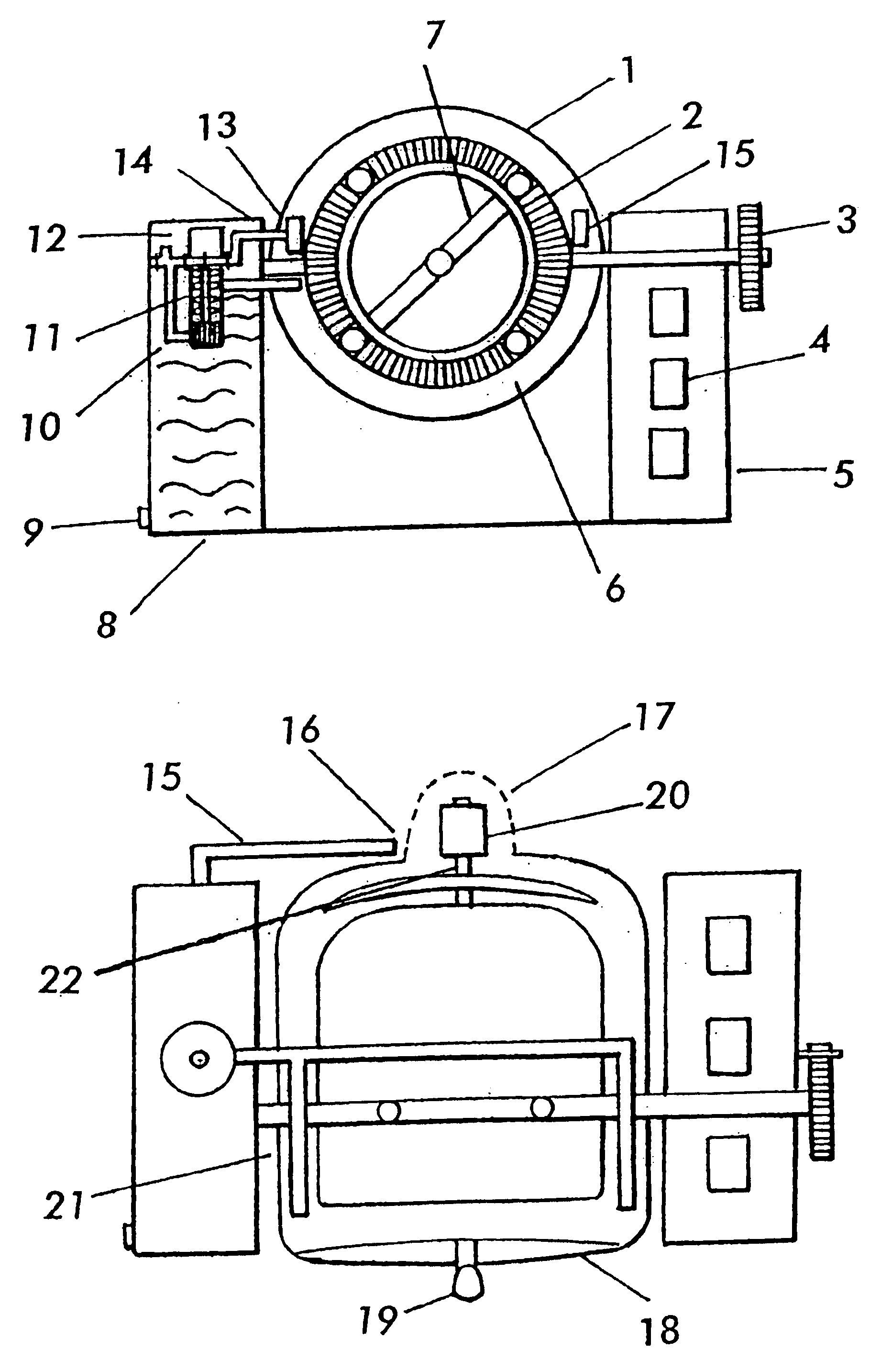
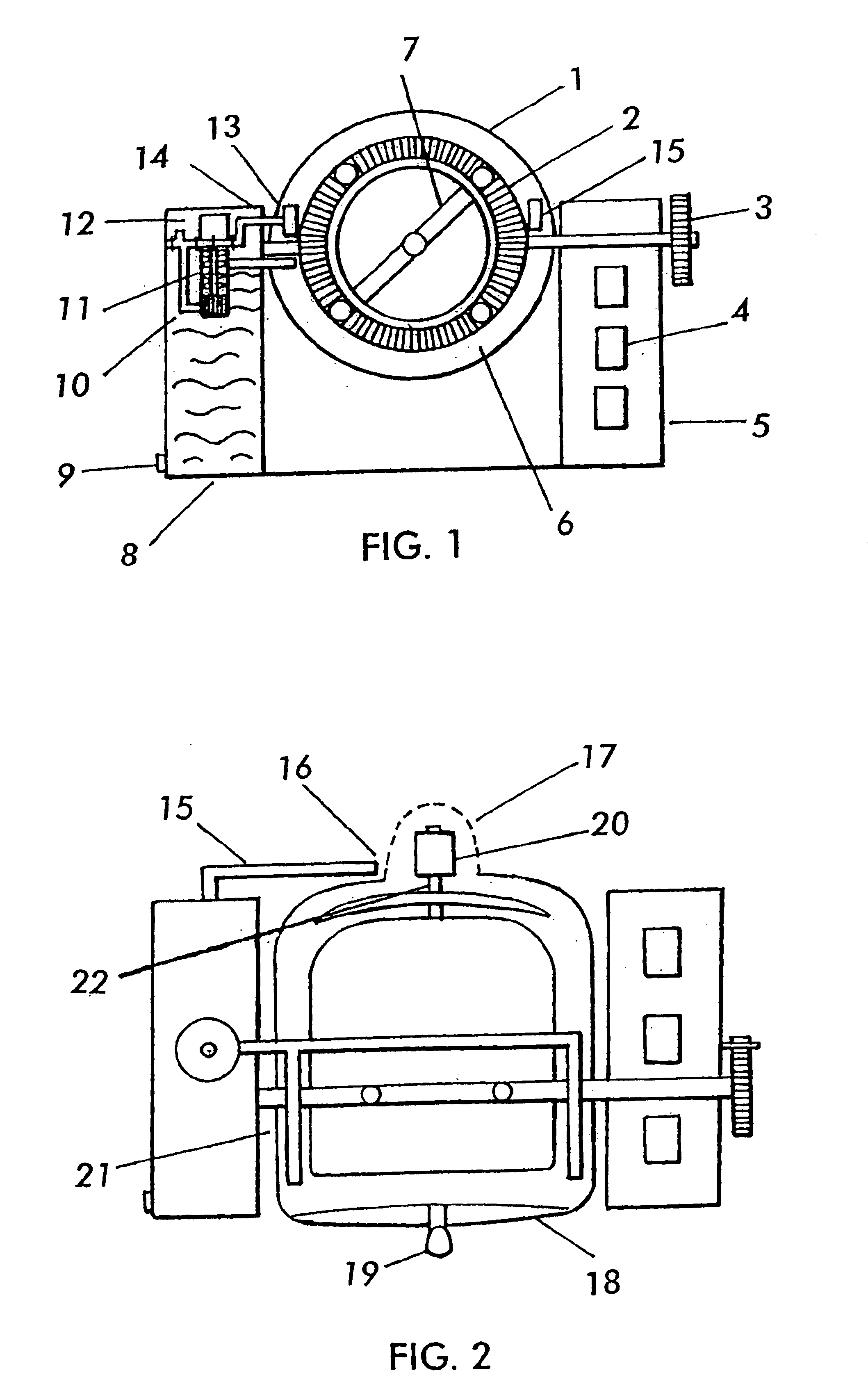
Hereinafter, the preferred embodiments will be described in detail with reference to the accompanying drawings.
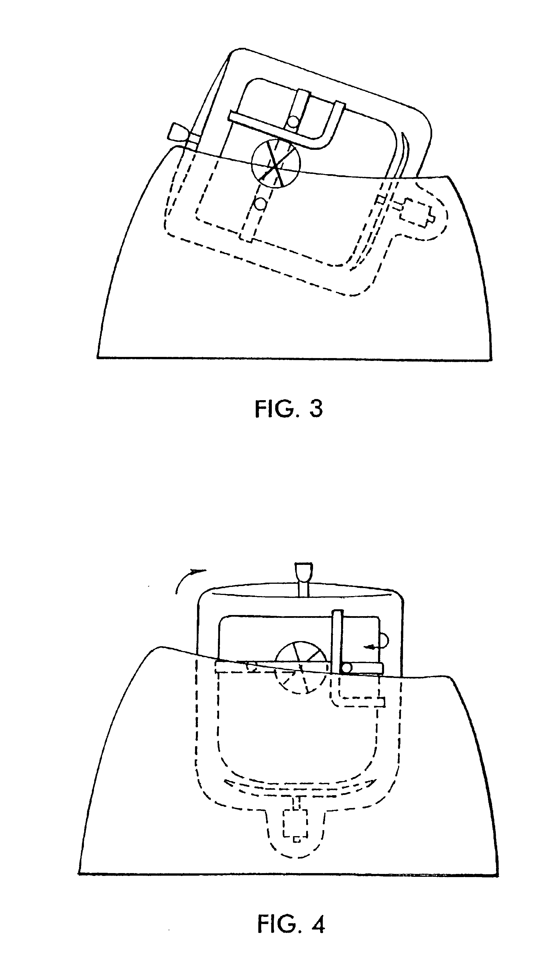
As shown in FIGS. 1 and 2, the automatic cooker is composed of a power motor 20 and a cooking body 2. A stirring rib 7 is provided inside the cooking body 2. A hollow semi-spherical food container (cooking body) 2 is inserted in the annular ring of the bearing structure (bearing ring 6). When the positioning hole (not shown) in the bottom of the cooking body 2 is attached to the positioning column 22 of the motor 20, the cooking body 2 can rotate in latitude direction (ditto, as shown in FIG. 4, wherein the cooking body is in vertical state) due to the rotation of the motor 20. It should be noted that this invention is not limited in this regard, as the cooking body 2 can rotate either in one single direction or bi-direction and either in successive state or in intermittent state. Furthermore, it can rotate along the longitudinal direction or latitudinal direction and either more than 360° or less than 360°. Two longitudinal shafts 21 are provided on the outer ring 6 of the bearing structure which rotates together with the housing 1 and motor 20 in synchronous state along longitudinal direction (shown in FIGS. 3 and 4). The roller 3 is adapted to control the rotation and the rotation angle of the cooking body. In this case, the rotation angle defined by the vertical central line and the horizontal plane is limited between 0 degree and 90 degrees. The housing 1 has a cover 18 with a handle 19.
The automatic cooker further includes a ventilator motor 12 which is connected to the blade assembly 11 of the ventilating fan. Air inlet is at 16, 17. The air there mixes with fumes. There is an outlet for gas and fumes at 13 and 15 through which the gas and fumes are conveyed by the ventilation for 11. In order to increase the pressure of it, the gas is introduced into water where the gas and fume are filtered out. The blade assembly 11 comprises at least two sets of blades. Air outflow ports 10 are provided on the side of the lower portion of the blade assembly 11 so that the gas sucked by the blade assembly 11 is introduced into water through air outflow ports 10. A pump 23 (as shown in FIG. 5) is mounted under air outflow ports 10. The pump 23 driven by ventilator motor 12 rotates in synchronized operation together with the blade assembly 11, thus water is sucked into the secondary filtering conduit (as shown in FIG. 5). After mixing with the fume and gas again in the secondary filtering conduit, the water returns to water tank 8 through water discharging ports c formed in the side of the secondary filtering conduit. With these configurations, the gas containing fume mixes with water and recycles continuously, thereby filtering out the fume and cooling the housing 1. In addition, the water containing fume in the water tank 8 is discharged outside from the water discharging port 9 and refilled periodically.
The automatic cooker according to the present invention also includes an electric oven 22 (as shown in FIG. 2) which is turned on/off in synchronized operation with the power supply unit of the ventilator motor 12.
FIG. 6 is a diagram schematically showing the controlling circuit of the automatic cooker. In the cooking process, the power is initiated and then a switch C1 is closed. As a result, the ventilator 12 rotates and the electric oven 22 starts to operate at the same time. Here, he switch C2 is closed and the power is applied to the relay K. Then, switch Kab is closed and the motor 20 of the electric pan is initiated so as to make the automatic cooker ready for cooking in a continuous state. On the other hand, the operator turns off the switch C2, then the automatic cooker shifts into the intermittent operation state in which once the operator touch the micro-active switch V, the motor stops for 10 seconds before it automatically restarts to rotate.

PUM

no PUM

Description & Claims & Application Information

We can also present the details of the Description, Claims and Application information to help users get a comprehensive understanding of the technical details of the patent, such as background art, summary of invention, brief description of drawings, description of embodiments, and other original content. On the other hand, users can also determine the specific scope of protection of the technology through the list of claims; as well as understand the changes in the life cycle of the technology with the presentation of the patent timeline. Login to view more.

Similar technology patents

Liquid crystal display panel

Owner:TCL CHINA STAR OPTOELECTRONICS TECH CO LTD

Counter-rotating axial flow fan

InactiveUS20110142611A1Enhance effectStatic pressure be enhancePropellersPump componentsEngineeringRazor Blade
Owner:THE UNIV OF TOKYO +2

Classification and recommendation of technical efficacy words

  • Prevent overheat
  • Enhance effect

Image forming apparatus

InactiveUS20090148173A1Prevent overheatHigh-quality image formationElectrographic process apparatusCorona dischargeControl functionEngineering
Owner:KYOCERA DOCUMENT SOLUTIONS INC

Key interlock device for vehicle

InactiveUS20110100075A1Prevent overheatAnti-theft devicesShaftsLocking plateEngineering
Owner:HYUNDAI MOTOR CO LTD +1

Impurities separation by distillation

InactiveUS6306263B1Prevent overheatReduce impurityOrganic compounds purification/separation/stabilisationEther separation/purificationReboilerOrganic matter
Owner:LYONDELL CHEM TECH LP

Prepreg, preform, molded product, and method for manufacturing prepreg

ActiveUS20110143110A1Reduce proportionEnhance effectSynthetic resin layered productsLaminationMechanical propertyIsotropy
Owner:TORAY IND INC

Methods and compositions for wound healing

ActiveUS20090263468A1Enhancement and/or promotionEnhance effectInorganic active ingredientsCapsule deliveryActive agentCharged polymers
Owner:IMBED BIOSCI
Why Eureka
Try Eureka