
Method and system for blind spot identification and warning utilizing visual indicators

a technology of visual indicators and blind spots, applied in the field of vehicle blind spot identification, can solve the problems of blind spot accidents, collisions between two vehicles, and it is nearly impossible to eliminate all blind spots with mirror adjustment, so as to improve the driver's awareness of the vehicl

Inactive Publication Date: 2009-03-05
IBM CORP
View PDF26 Cites 84 Cited by
  • Summary
  • Abstract
  • Description
  • Claims
  • Application Information

AI Technical Summary

Benefits of technology

[0011]As a result of the summarized invention, a solution is technically achieved for a method and syste

Problems solved by technology

A major contributor to vehicle accidents is blind spots in the rear side perspective views of a driver.
Blind spot accidents occur when a driver switches lanes and is unaware that a second vehicle is occupying the intended new lane.
As a result, a collision between the two vehicles occurs.
However, it is nearly impossible to eliminate all blind spots with mirror adjustment.
Tractor-trailer drivers encounter a much larger visual impairment.
In the US, over 200,000 accidents between cars and trucks occur each year.

Method used


Image

  • Method and system for blind spot identification and warning utilizing visual indicators
  • Method and system for blind spot identification and warning utilizing visual indicators
  • Method and system for blind spot identification and warning utilizing visual indicators

Examples


Embodiment Construction

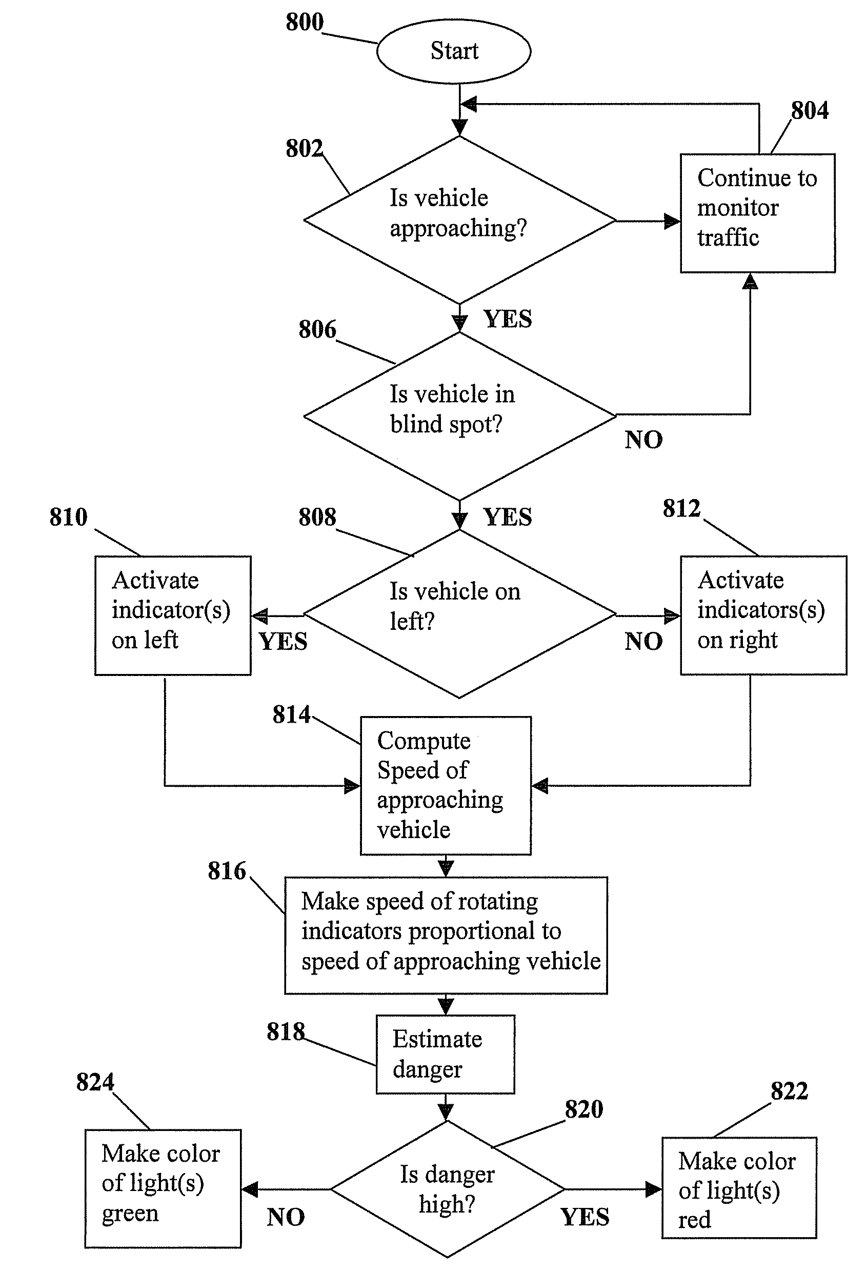
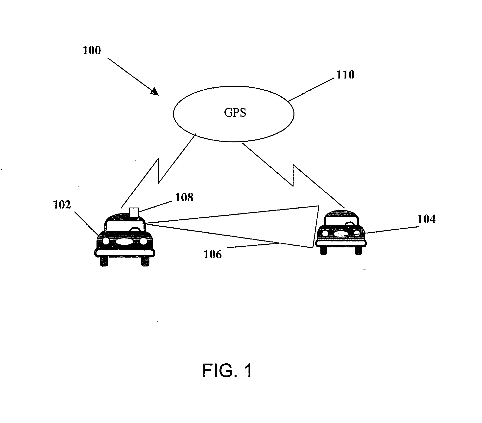
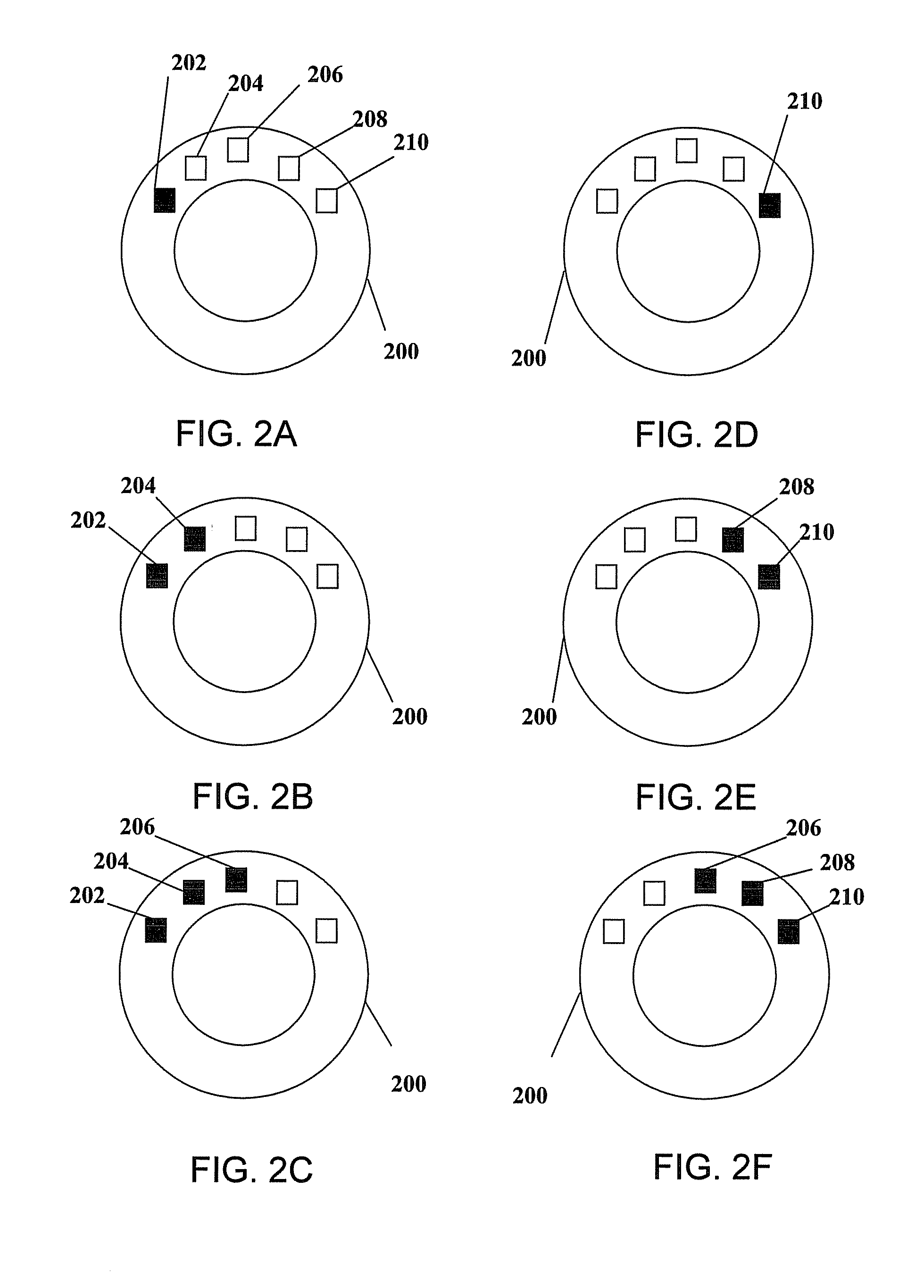
[0022]Embodiments of the invention provide a method and system for providing a driver of a vehicle a warning of the approach into and the presence of another vehicle in the driver's blind spot. The blind spot warning system utilizes a series of sensors attached to the driver's vehicle, forms of radar, and global positioning system (GPS) satellites to detect the presence and relative position of vehicles to a driver's blind spot. The series of sensors are connected to a blind spot warning device. In embodiments of the invention, the blind spot warning device issues a warning to the driver of the vehicle through a series of indicators in the form of lights embedded in the steering wheel, dashboard, mirrors, or projected onto the windshield in front of the driver. The indicator lights may take the form of, but are not limited to, light emitting diodes (LED), liquid crystal display (LCD), plasma, and electroluminescent elements elements. Embodiments of the invention indicate whether veh...


PUM


Abstract

A method for detecting and alerting a driver of vehicles in their blind spots, includes: tracking movement and relative position of a driver to one or more vehicles; determining one or more driver blind spots; determining when at least one of the one or more vehicles approaches one of the driver blind spots; determining when at least one of the one or more vehicles occupies one of the driver blind spots; activating one or more indicators in response to one or more vehicles approaching and occupying one of the driver blind spots; wherein the one or more indicators comprise light emitting diodes (LED), liquid crystal display (LCD), plasma, projected elements, and electroluminescent elements; and wherein a sequence and pattern of activating the one or more indicators is determined based on the relative position of the driver to the one or more vehicles.

Description

TRADEMARKS[0001]IBM® is a registered trademark of International Business Machines Corporation, Armonk, N.Y., U.S.A. Other names used herein may be registered trademarks, trademarks or product names of International Business Machines Corporation or other companies.BACKGROUND OF THE INVENTION[0002]1. Field of the Invention[0003]This invention relates generally to vehicle blind spot identification, and more particularly to a method and system for alerting a driver to the presence of vehicles in their blind spot.[0004]2. Description of the Related Art[0005]A major contributor to vehicle accidents is blind spots in the rear side perspective views of a driver. The driver blind spots occur when a second vehicle is traveling slightly behind and along side the driver's vehicle in an accompanying lane. Blind spot accidents occur when a driver switches lanes and is unaware that a second vehicle is occupying the intended new lane. As a result, a collision between the two vehicles occurs. Driver...

Claims


Application Information

Patent Timeline
IPC IPC(8): G06F19/00
CPCG08G1/16B60Q9/008G08G1/167
Inventor BASSON, SARA H.KANEVSKY, DIMITRIKELLEY, EDWARD E.WEST, FRANCES
Owner IBM CORP
Features
  • Generate Ideas
  • Intellectual Property
  • Life Sciences
  • Materials
  • Tech Scout
  • Unparalleled Data Quality
  • Higher Quality Content
  • 60% Fewer Hallucinations
Learn More