
Structure of Supporting Rotation Shaft

a technology of rotating shaft and supporting rack, which is applied in the direction of hinges, machine supports, manufacturing tools, etc., can solve the problem that the kind of supporting rack cannot be used in a big flat panel monitor

Active Publication Date: 2009-03-12
JARLLYTEC CO LTD
View PDF11 Cites 4 Cited by
  • Summary
  • Abstract
  • Description
  • Claims
  • Application Information

AI Technical Summary

Benefits of technology

[0010]Another object of the present invention is to provide a structure of supporting rotation shaft rod, wherein an axial tube is provided between the two sheet flanks, the top end of the axial tube is radially provided with a through hole for allowing a conventional connecting unit pass through, so the conventional connecting unit can be fixed at a connecting hole predetermined at the center of the retaining shaft rod.

Problems solved by technology

But for one with a larger size, e.g. a 15-inch flat panel monitor or even a bigger one, the supportive rack is deemed as a bit too simple; for example, there is no resilient supporting unit provided so a function of adjusting the tilting angle is not available, so this kind of supporting rack can not be used in a big flat panel monitor.

Method used


Image

  • Structure of Supporting Rotation Shaft
  • Structure of Supporting Rotation Shaft
  • Structure of Supporting Rotation Shaft

Examples


Embodiment Construction

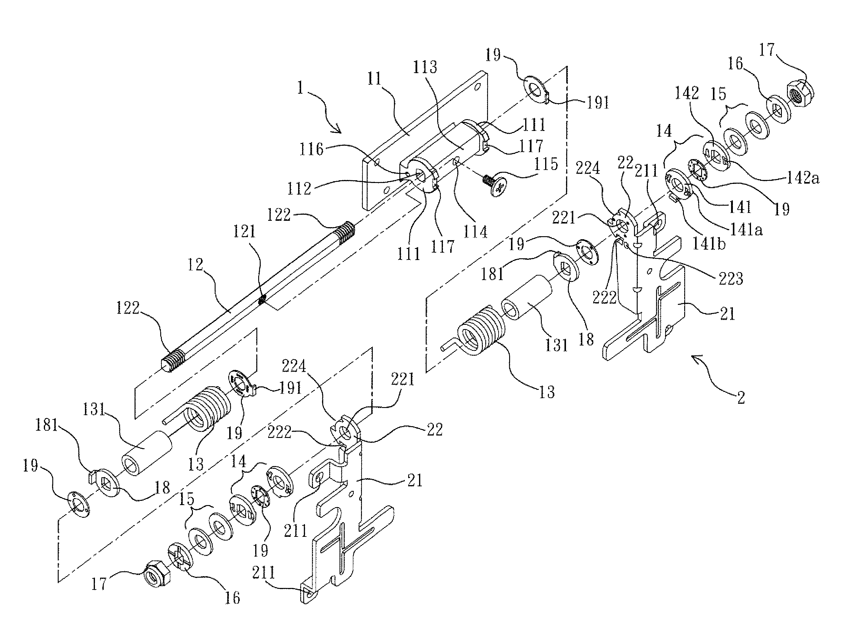
[0023]As shown from FIG. 1 to FIG. 3, the structure of supporting rotation shaft provided by the present invention is composed by a retaining member I and a mobile supporting member 2.

[0024]A pair of sheet flanks 111 are protrudingly provided on a surface of a retaining sheet 11 of the retaining member 1, a round shaped shaft hole 112 is respectively provided to each of the sheet flanks 111 for allowing a retaining shaft rod 12 axially pass through. As shown in FIG. 1, the retaining sheet 11 is formed by casting; in order to enhance the connecting strength between the retaining shaft rod 12 and the two sheet flanks 111, an axial tube 113 is provided between the two sheet flanks 111, and the top end of the axial tube 113 is radially provided with a through hole 114 for allowing a conventional connecting unit 115, e.g. a screw, pass through, so the conventional connecting unit 115 is fixed at a connecting hole 121 predetermined at the center of the retaining shaft rod 12, so the retai...


PUM


Abstract

The present invention relates to a structure of supporting rotation shaft, comprises a retaining member, a surface of a retaining sheet of the retaining member is protrudingly provided with a pair of sheet flanks that allow a retaining shaft rod pass through, two ends of the retaining shaft rod are respectively provided with a resilient supporting unit, two ends of each of the resilient supporting units are respectively connected to the retaining member and a mobile supporting member; the mobile supporting member mention above, two lugs adjacently to the corresponding resilient supporting units are protrudingly provided on two top ends of two supporting racks of the mobile supporting member, each of the lugs is passed through by the retaining shaft rod, two ends of the retaining shaft rod are respectively provided with a latching unit, each of the latching units is composed by a mobile buckling sheet provided at the outer side of each of the lugs and a retaining buckling sheet that allows the retaining shaft rod pass through and be positioned, two opposite surfaces of one of the mobile buckling sheets and the corresponding retaining buckling sheet are respectively and protrudingly provided with a pair of mobile protruding bumps and a pair of retaining protruding bumps, two ends of the retaining shaft rod are further and respectively provided with at least one resilient unit and then is connected to an end sealing member; by pulling the mobile supporting member, the pair of mobile protruding bumps of one of the mobile buckling sheets pass across the pair of retaining protruding bumps of the retaining buckling sheet provided adjacently to the mobile buckling sheet, so a storing status of the mobile supporting member is released and an initial operation status is therefore formed.

Description

BACKGROUND OF THE INVENTION[0001]1. Field of the Invention[0002]The present invention relates to a structure of rotation shaft, more particularly to a structure of supporting rotation shaft which can be served as a supporting rack for a rear portion of an object to be supported and the tilting angle of the object to be supported is capable of being adjusted.[0003]2. Description of Related Art[0004]Two connected members having a relative connection angle are commonly seen and used in now days, such as door sheets; opening and closing two members are often defined as in an operating status and a non-operating status, e.g. a note book computer, an electronic dictionary, a portable audio / video displaying device.[0005]The device whose relative angle can be adjusted often is mainly composed by a hinge; when applied to the note book computer mentioned above, the device is defined as a rotation shaft or a hinge device; regardless the definition of the device, theories of torque and friction...

Claims


Application Information

Patent Timeline
Patent Type & Authority Applications(United States)
IPC IPC(8): E05D11/10E05D5/12
CPCF16M11/10F16M13/02Y10T16/540345Y10T16/54021F16M2200/041
Inventor TANG, CHUNG-HSUNCHENG, KANG HAN
Owner JARLLYTEC CO LTD
Learn More