Curved implantable sheath and method of making same

a technology of implantable sheaths and curved edges, which is applied in the field of curved implantable sheaths, can solve the problems of abnormal development of the left ventricle and may be virtually absen

Inactive Publication Date: 2004-02-03
GABBAY SHLOMO
View PDF7 Cites 207 Cited by
  • Summary
  • Abstract
  • Description
  • Claims
  • Application Information

AI Technical Summary

Problems solved by technology

Also as a consequence of limited outflow from the heart, the left ventricle develops abnormally and may be virtually absent.
Because certain curved shapes are difficult to reproduce, a generally flat sheath of biocompatible tissue typically is used for many types of procedures.

Method used


Image

  • Curved implantable sheath and method of making same
  • Curved implantable sheath and method of making same
  • Curved implantable sheath and method of making same

Examples


Embodiment Construction

Various illustrative aspects of the present invention will now be described in connection with the following figures.

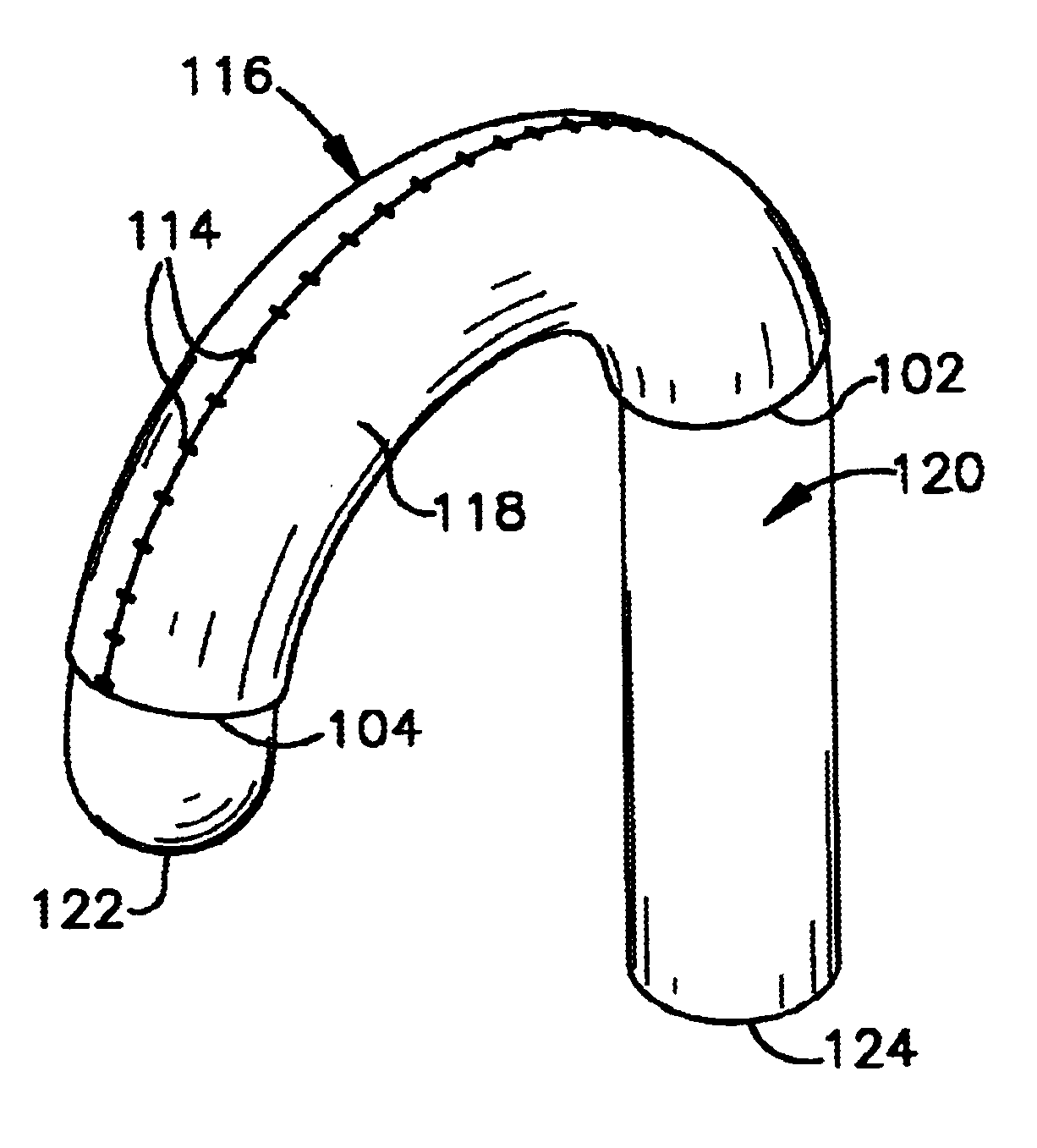
The present invention provides a system and method that may be used to fix tissue to a desired shape so as to better conform to contoured organs and tissue against which the tissue is to engage when implanted. While the following examples will be described with respect to forming a calotte-shaped sheath of tissue, those skilled in the art will understand and appreciate that other shapes, such as cylindrical sheaths and curved arches, also may be formed in accordance with the present invention.

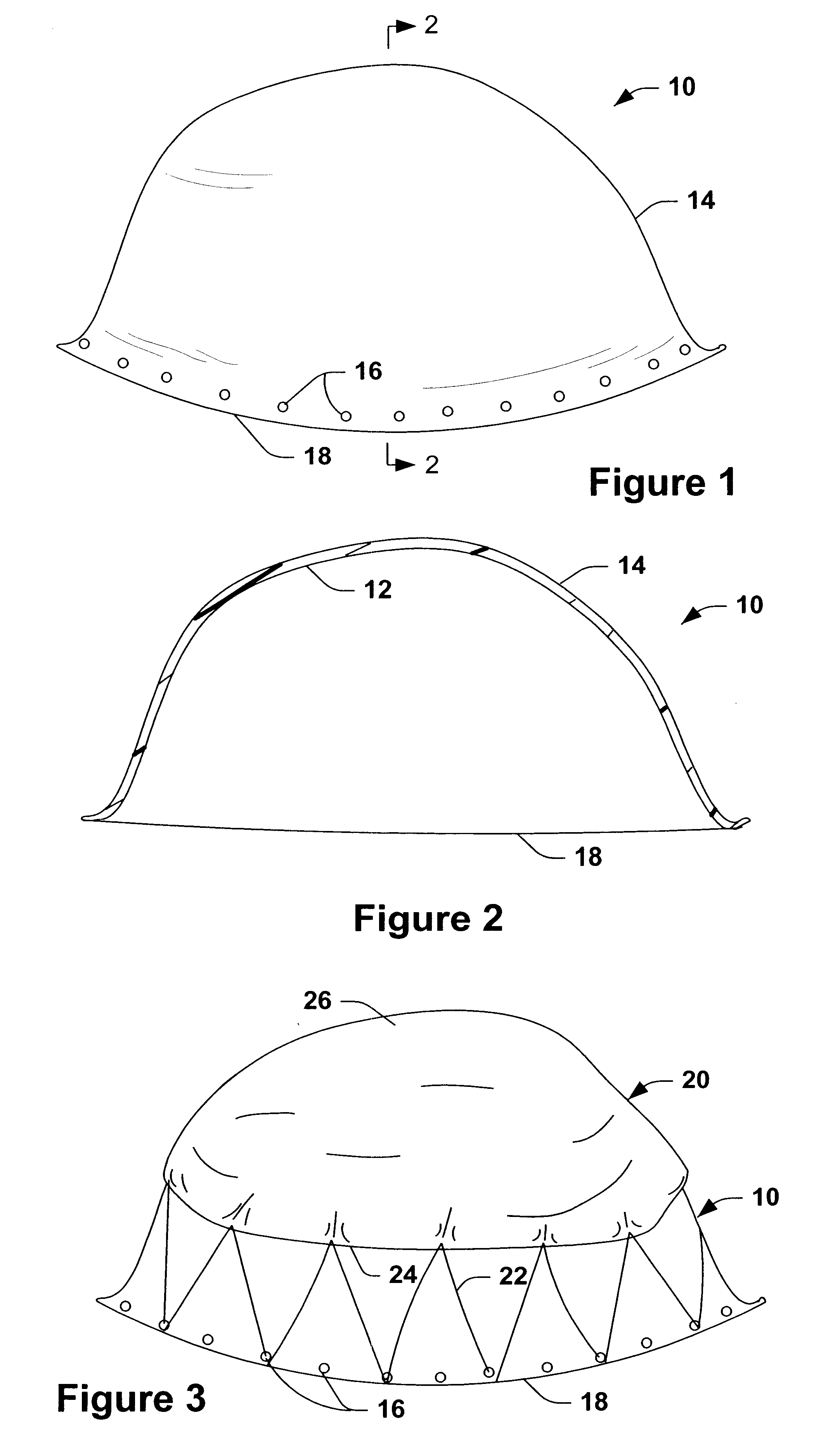
Turning now to FIGS. 1 and 2, a generally semi-spherical base 10 is illustrated. The base 10, which may be a bowl formed of a rigid material (e.g., a metal or plastic material), has an inner surface 12 and an outer surface 14. In this example, the inner surface 12 is curved in a convex manner and the outer surface 14 is curved in a generally concave manner.

In accordance with an a...


PUM

PropertyMeasurementUnit
diameteraaaaaaaaaa
timeaaaaaaaaaa
diameteraaaaaaaaaa

Abstract

A method for making a curved implantable sheath includes placing a sheet of flexible material into engagement with a member having a curved surface having a desired configuration. The sheet and member are placed in a fixation solution so that the sheet assumes the configuration of the surface engaged thereby.

Description

The present invention relates to implantable tissue and, more particularly to a curved implantable sheath and to a method for making a curved sheath.Various configurations of implantable structures are employed to help repair diseased and malformed organs and other tissue. By way of example, congenital cardiac malformations as well as other diseased conditions, require treatment, which can include drug therapy and / or surgery. Often times, it is necessary to replace or reconstruct an artery or other major vessel, such as the aorta or pulmonary artery.In one particular condition, known as hypoplastic left heart syndrome, severe aortic valve hypoplasia and / or aortic valve atresia develop. As a result of such conditions, the aorta may be significantly underdevelop, providing a rudimentary ascending aorta having a diameter of about one to about four millimeters. Also as a consequence of limited outflow from the heart, the left ventricle develops abnormally and may be virtually absent.Bec...

Claims


Application Information

Patent Timeline
Patent Type & Authority Patents(United States)
IPC IPC(8): A61F2/06A61F2/04A61L27/36A61L27/00A61B17/00A61F2/00
CPCA61F2/0063A61F2/04A61F2/06A61F2/062A61L27/36A61B2017/00243Y10S623/901A61L27/3604
Inventor GABBAY, SHLOMO
Owner GABBAY SHLOMO
Why Eureka
Try Eureka