
Method of manufacturing prismatic battery

a manufacturing method and prismatic battery technology, applied in the field of prismatic batteries, can solve the problems of unreliable sealing properties, prone to breakage of bent gaskets, and difficult to achieve concentricity between electrode poles and support cylinders, and achieve satisfactory end face flatness, high reliability of sealing structure, and sufficient weld strength

Inactive Publication Date: 2009-03-12
PANASONIC CORP
View PDF6 Cites 7 Cited by
  • Summary
  • Abstract
  • Description
  • Claims
  • Application Information

AI Technical Summary

Benefits of technology

The present invention provides a prismatic battery with a highly reliable sealing structure for the part where an electrode pole or terminal passes through the battery case lid. The battery uses a lightweight lid that is welded to the case with a support cylinder, which ensures a good seal and prevents uneven compression of the insulating gasket. The battery is manufactured with good productivity and can be produced in different capacities and lengths. The method for manufacturing the battery includes preparing an electrode plate group, welding a current collector to one end of the electrode plate group, and hermetically welding a lid to the open end of the case. The battery case has an open end for accommodating an electrode plate group, and the electrode pole is connected to the current collector using a buffer, which absorbs positional errors and provides a smooth seal. The invention provides a reliable sealing structure and efficient production of prismatic batteries with good productivity.

Problems solved by technology

With this method, there was the risk that cracks were generated in the gasket when crimping the support cylinder, leading to unreliable sealing properties.
Also, the bent portion of the gasket was liable to break due to an impact external force.
Another problem was that, since the electrode pole, which was rigidly attached to the current collector, was fitted into the support cylinder formed on the lid, it was hard to achieve concentricity between the electrode pole and the support cylinder because of dimensional tolerances of the current collector and the electrode pole and dimensional errors of the case and lid.
When the electrode pole and the support cylinder are not concentric with each other, the pressure is applied unevenly to the gasket when crimping the cylinder, whereby an adequate seal can not be formed because of insufficient compression of the gasket or because of breakage of the gasket caused by excessive compression.
The problem with the laser welding processes for prismatic battery cases shown in Japanese Patent Laid-Open Publications No. 8-315790 or No. 7-272701 was that, while the thick flat lid 52 was suitable for forming a strong weld 53 without impairing the flatness of the case 51 end face or the lid 52, its weight took up much of the battery weight because of its large thickness that was for withstanding pressure buildup to a predetermined level.
This not only impairs the flatness of the case end face, but also may cause electrolyte leakage because of weld failure.
With the deep drawing techniques shown in Japanese Patent Laid-Open Publications Nos. 5-109393, 9-237613, and 2003-208876, it was hard to produce bottomed cases with a large height while maintaining necessary productivity.
Another problem with deep drawing methods was that it did not allow much freedom of design for battery capacities because it was difficult to produce bottomed cases of various heights in view of negative cost factors such as required production equipment and change-over time.

Method used


Image

  • Method of manufacturing prismatic battery
  • Method of manufacturing prismatic battery
  • Method of manufacturing prismatic battery

Examples


Embodiment Construction

[0049]Preferred embodiment of the present invention will now be described below with reference to the accompanying drawings. It should be noted that the embodiments described below do not intend to limit the scope of the present invention, but exemplify the invention.

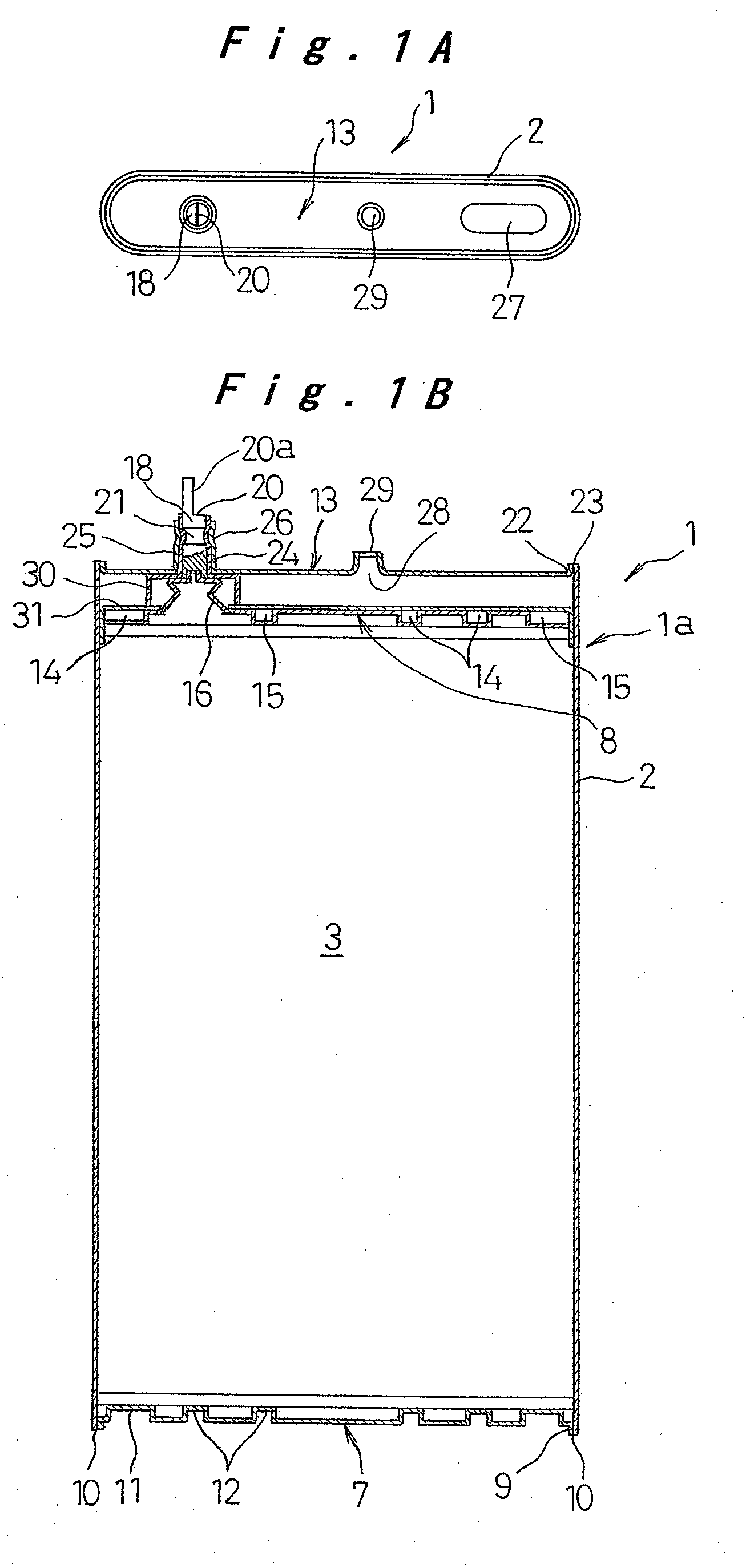
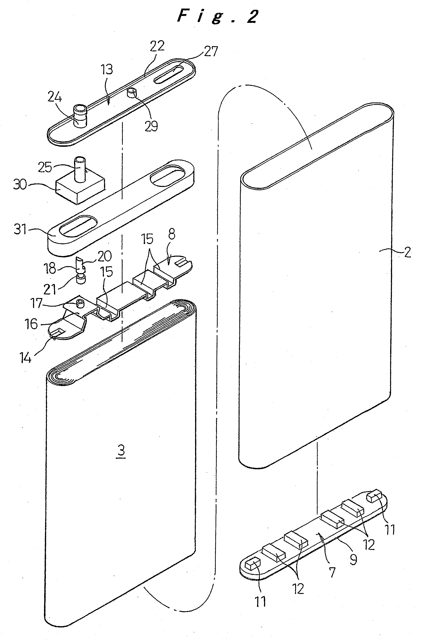
[0050]One of preferred embodiments of the prismatic battery of the invention will be described hereinafter with reference to FIG. 1A to FIG. 13.

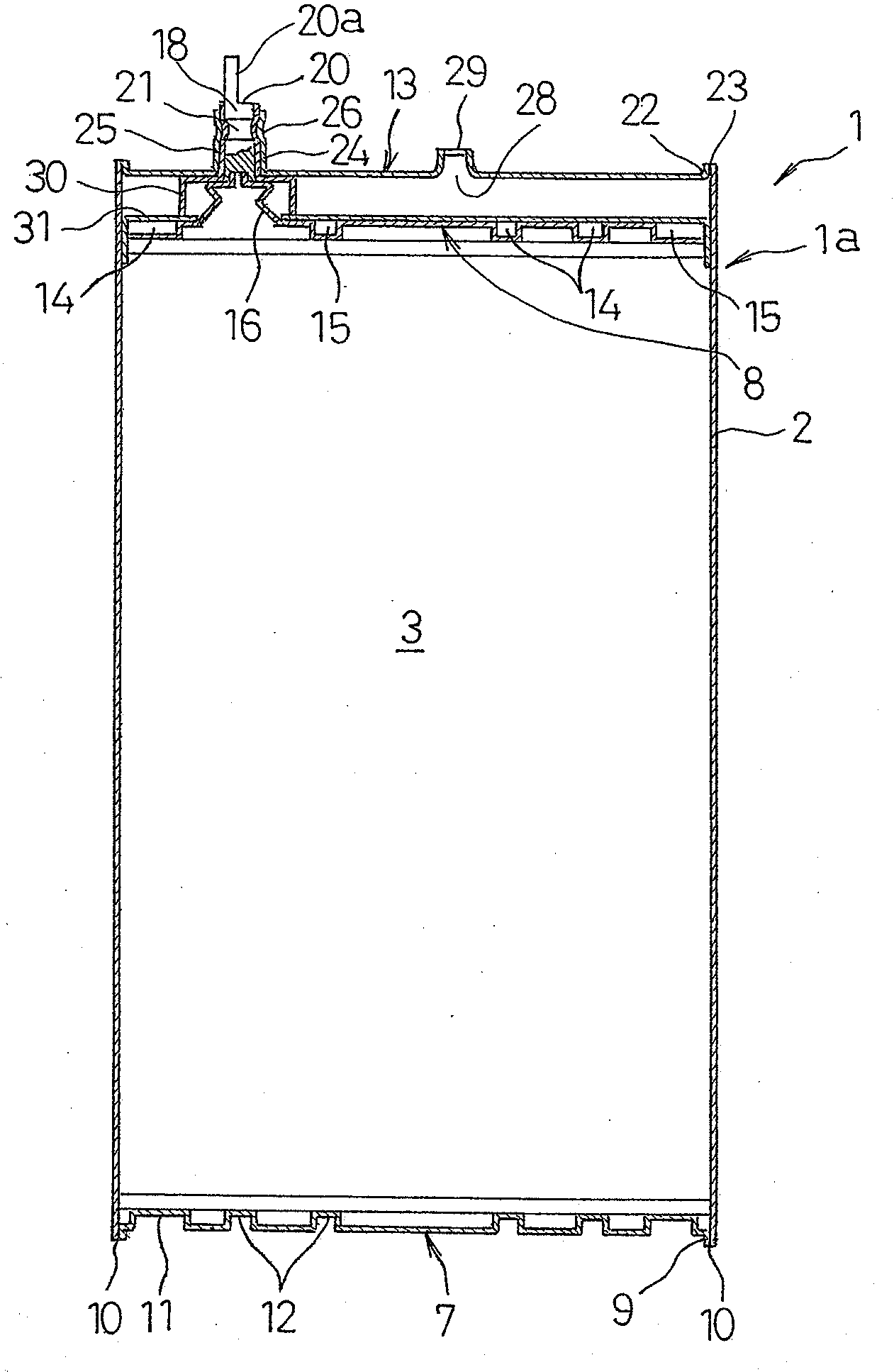
[0051]FIGS. 1A to 2 illustrate a prismatic lithium battery 1 generally consisting of a battery case 1a and elements for electromotive force or an electrode plate group 3 encapsulated in the case 1a with electrolyte. The battery case 1a is made by hermetically welding an upper lid 13 and a lower lid that also functions as a positive collector 7 as will be described later to open ends of a substantially square tube case 2 that has a flat rectangular, round rectangular, or oval cross section.

[0052]FIGS. 12A to 12D illustrate how the square tube case 2 is made from a cylindrical tub...


PUM

PropertyMeasurementUnit
pressureaaaaaaaaaa
shapeaaaaaaaaaa
polarityaaaaaaaaaa

Abstract

A prismatic battery with highly reliable sealing properties and its manufacturing method, wherein a negative collector is welded to one end of an electrode plate group accommodated in a prismatic case, the collector being connected to an electrode pole that functions as the negative electrode terminal, and the electrode pole is fitted into a support cylinder that is provided on an upper lid for closing one open end of the case. An insulating gasket is interposed between an inner periphery of the support cylinder and an outer periphery of the electrode pole, the support cylinder being formed with at least one annular crimped portion that has an arc-shaped longitudinal cross section.

Description

CROSS-REFERENCE TO RELATED APPLICATIONS[0001]This application is a divisional of U.S. patent application Ser. No. 10 / 996,450 filed on Nov. 26, 2004, which claims priority to Japanese Application Nos. 2003-398482, 2003-398841, 2003-406878, 2004-173422 and 2004-187463, filed on Nov. 28, 2003, Nov. 28, 2003, Dec. 5, 2003, Jun. 11, 2004, and Jun. 25, 2004, respectively, the contents of which are herein expressly incorporated by reference in their entirety.BACKGROUND OF THE INVENTION[0002]1. Field of the Invention[0003]The present invention relates to a prismatic battery that has a rectangular, round rectangular, or oval cross section and to its manufacturing method, and more particularly to an electrode terminal structure of the battery.[0004]2. Description of the Related Art[0005]Japanese Utility Model Laid-Open Publication No. 6-45253 shows a sealing structure of a battery that has an electrode pole as one terminal, and a battery case serving as the other terminal. The electrode pole ...

Claims


Application Information

Patent Timeline
Patent Type & Authority Applications(United States)
IPC IPC(8): H01M6/02H01M50/169H01M50/541
CPCH01M2/0232Y10T29/4911Y10T29/49114H01M2/0413Y02E60/10H01M50/174H01M50/171Y02P70/50H01M50/169
Inventor HASHIMOTO, TATSUYANAGATANI, MASATOMOICHINOSE, HIROAKI
Owner PANASONIC CORP
Learn More