Package structure for display device

a display device and packaging technology, applied in the direction of damagable goods packaging, packaging goods type, transportation and packaging, etc., can solve the problems of increasing the number of parts, increasing the design time, and the structure described above still has the problem of cost increase, so as to reduce the cost increase, increase the design time, and increase the number of parts

Inactive Publication Date: 2009-03-12
MITSUBISHI ELECTRIC CORP
View PDF18 Cites 23 Cited by
  • Summary
  • Abstract
  • Description
  • Claims
  • Application Information

AI Technical Summary

Benefits of technology

[0008]An object of the invention is to provide a package structure for a display device, which structure minimizes cost increase due to increased design time and an increased number of parts and prevents an optical sheet from being brought into contact with the display panel and making scratches on the display panel due to motion caused during transport of the display device.

Problems solved by technology

However, the structure described above still has the problem of cost increase due to increased design time and an increased number of parts, because the backlights 2 must be arranged at different pitches and parts of different dimensions are necessary for the supports 8 arranged from top to bottom.

Method used


Image

  • Package structure for display device
  • Package structure for display device
  • Package structure for display device

Examples


Embodiment Construction

[0017]Now, a preferred embodiment of the invention is concretely described with reference to the drawings.

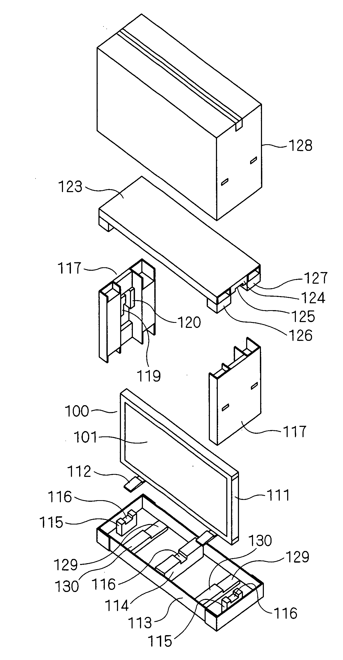
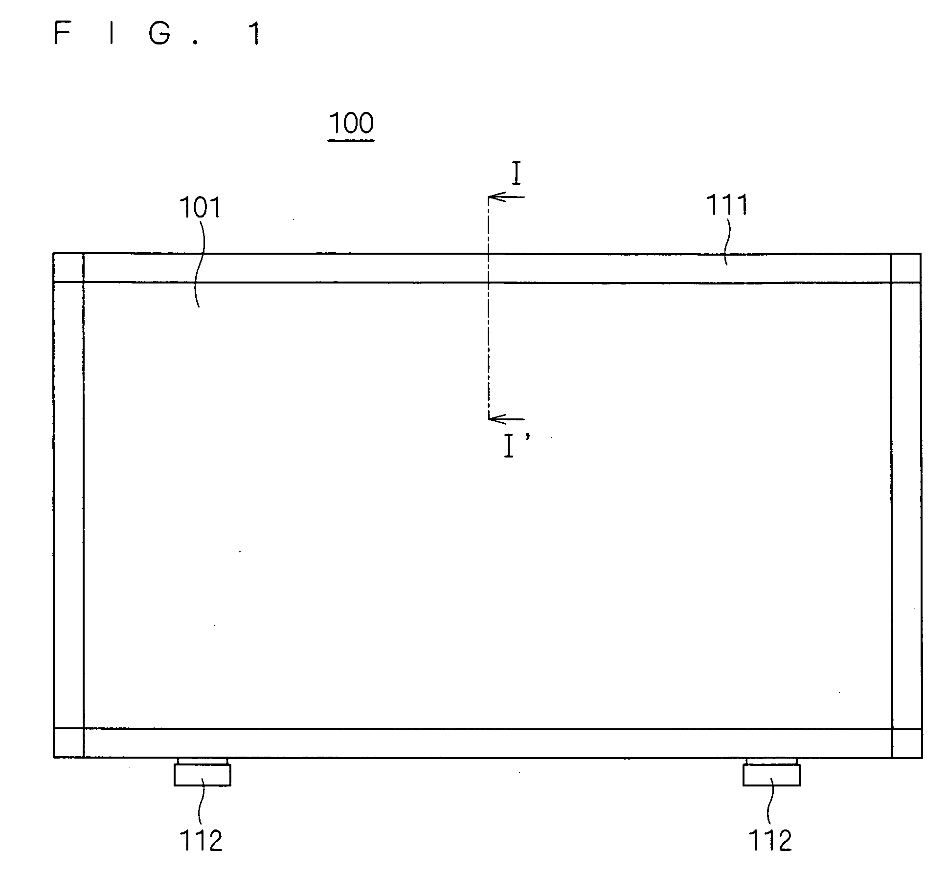
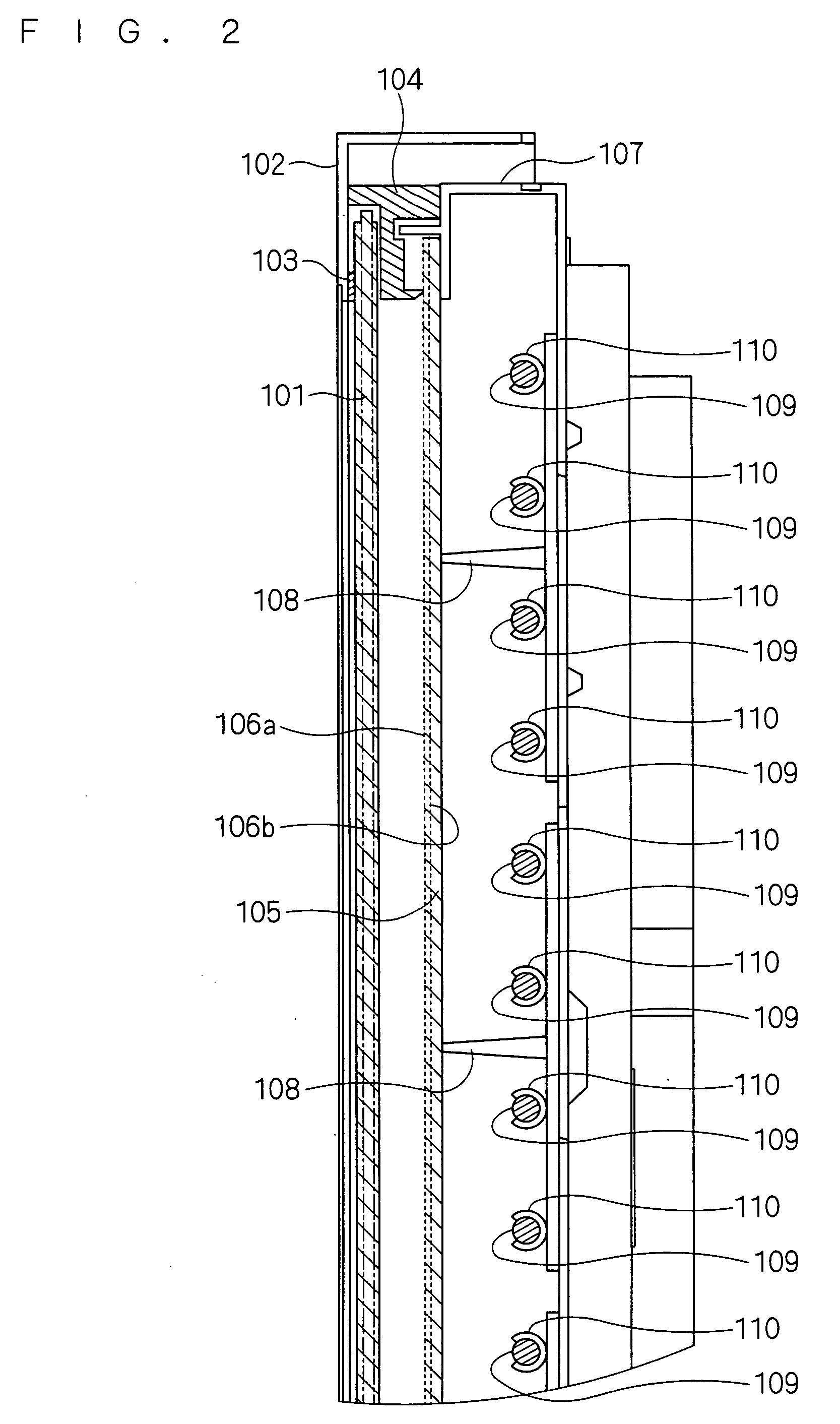
[0018]FIG. 1 is a front view of a thin display device 100 of a first preferred embodiment of the invention, and FIG. 2 is a cross-sectional view showing the essential parts taken by line I-I′ in FIG. 1. As shown in FIG. 2, a display panel 101 has its outer rim held between a cushion 103 and a spacer 104 that are fixed inside a first frame 102; optical sheets 106a and 106b and a diffuser plate 105 that diffuses illumination emitted from backlights 109 have their outer rims held between a second frame 107 and the spacer 104; and the display panel 101, the diffuser plate 105, and the optical sheets 106a and 106b are situated in approximately parallel with a display surface.

[0019]The second frame 107 have a plurality of supports 108 of the same size formed thereon at regular intervals. On the bottom of each of the supports 108, four retaining members 110 of the same size that hold t...


PUM


Abstract

A package structure prevents an optical sheet from being brought into contact with a display panel and making scratches on the display panel due to motion caused during transport of a display device, thereby minimizing cost increase. A package structure for a thin display device is the structure for storing the thin display device in a package case. The thin display device includes at least one optical sheet situated in approximately parallel with its display surface, and the package case includes a storage member for holding a thin display device with the optical sheet having a surface inclined relative to a vertical direction.

Description

BACKGROUND OF THE INVENTION[0001]1. Field of the Invention[0002]The invention relates to a package structure for a display device with an optical sheet.[0003]2. Description of the Background Art[0004]Conventional liquid crystal displays are configured for example as shown in FIG. 2 of Japanese Patent Application Laid-open No. 2007-17737. That is, a display panel 1 is held vertically by a first frame member 403 and a second frame member 402 mounted inside the first frame member 403. A diffuser plate 301 and an optical sheet 302 are mounted at an angle so as to allow a wide space between themselves and the upper part of the display panel 1 with respect to the direction of their weight, with their upper ends held between a first spacer 404 and a third frame member 401 and their lower ends held between a second spacer 405 and the second frame member 402.[0005]Backlights 2 mounted behind the diffuser plate 301 have different pitches from one another according to their corresponding inter...

Claims


Application Information

Patent Timeline
Patent Type & Authority Applications(United States)
IPC IPC(8): B65D85/38
CPCB65D2585/6837B65D81/113
Inventor KAKUTA, YOSHINORITAKEUCHI, SHIGERUTAGUCHI, HIROKAZUKANNO, NAOKINISHIKAWA, KIMITO
Owner MITSUBISHI ELECTRIC CORP
Why Eureka
Try Eureka