Anti-Asphyxia Valve Assembly for Respirator Mask

a technology of respirator mask and valve assembly, which is applied in the direction of valve details, valve arrangement, valve housing, etc., can solve the problems of incorrect assembly/alignment, inadvertent assembly without, and incorrect re-assembly

Active Publication Date: 2009-03-12
RESMED LTD
View PDF16 Cites 104 Cited by
  • Summary
  • Abstract
  • Description
  • Claims
  • Application Information

AI Technical Summary

Benefits of technology

[0011]According to yet another aspect of the invention, there is provided an elbow assembly for a mask, comprising: an elbow having a first portion structured to engage with a mask frame and a second portion structured to receive pressurized gas; a first gas path defined between the first and the second portions; a port in communication with atmosphere and in selective communication with the first portion of the elbow; a second gas path defined between the first portion and the port; and an anti-asphyxia valve (AAV) assembly, said AAV assembly including a flap portion and a frame assembly integrally supporting the flap portion, the flap portion being movable to selectively open and close the port, wherein said flap portion assumes a closed position when pressurized gas less than or equal to a predetermined threshold is delivered to the second portion of the elbow, in which case the port can communicate with the first portion via the second gas path, and said flap assumes an open position when pressurized gas above the predetermined threshold is delivered to the second portion, in which case the flap portion seals the port and the first portion is in communication with the second portion via the first gas path.
[0012]According to still another aspect of the present invention, there is provided a mask assembly comprising a frame; an elbow provided to the frame; and an anti-asphyxia valve (AAV) assembly secured within the elbow upon assembly of the elbow to the frame.
[0013]According to yet another embodiment of the present invention, there is provided an elbow assembly comprising an elbow, the elbow having a first portion adapted to be secured to a mask and a second portion adapted to receive pressurized gas, the first and the second portions having connection structure allowing selective connection and disconnection between the first and second portions, the connection structure including a pair of resilient arms provided on one of the first and second portions and a flange provided on the other of the first and second portions, each of the arms including a claw to lock with the flange; and an anti-asphyxia valve (AAV) assembly provided within the elbow and sandwiched between the first and second portions.

Problems solved by technology

(a) inadvertent assembly without one or more of the safety devices;
(b) incorrect assembly / alignment; and / or
(c) incorrect re-assembly following inadvertent dis-assembly during the course of treatment.
If the flow generator's operation is interrupted as a result of power outage or other mechanical / electrical failure, there may be a significant build up of carbon dioxide in the mask as the patient's exhaled air is not washed out of outlet vents that are usually provided to the mask assembly.
This may present a health risk to the patient.

Method used


Image

  • Anti-Asphyxia Valve Assembly for Respirator Mask
  • Anti-Asphyxia Valve Assembly for Respirator Mask
  • Anti-Asphyxia Valve Assembly for Respirator Mask

Examples


ninth embodiment

2.9 Ninth Embodiment

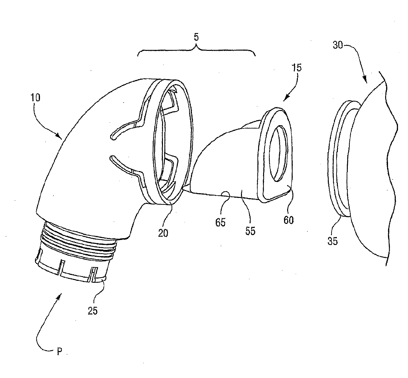
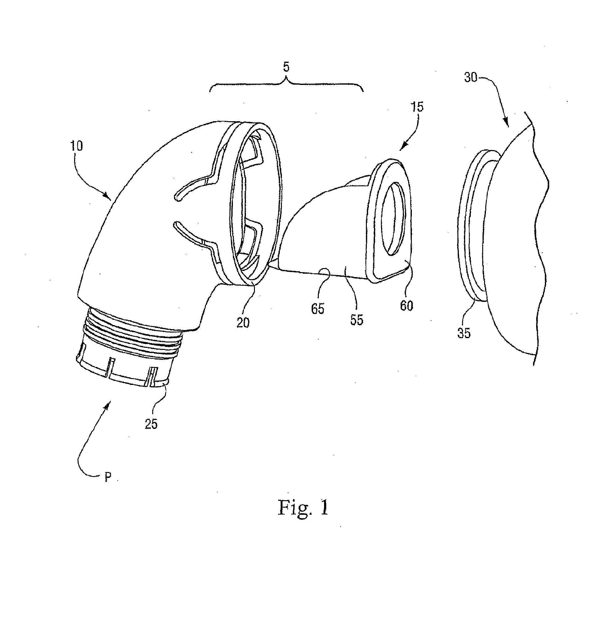
[0163]FIGS. 90-111 illustrate an elbow assembly 5 according to another embodiment of the present invention. As illustrated, the elbow assembly 5 includes an elbow 10, an AAV assembly 15, and a clip member 200 to secure the AAV assembly 15 to the elbow 10.

[0164]This embodiment is similar to the elbow assembly 5 shown in FIGS. 68-89. In contrast, the elbow assembly 5 of FIGS. 90-111 includes two rigid tabs 430 integrally molded with the elbow 10 to prevent over-extension of the elongated snap-fit tabs 408 during disassembly and thereby prevent their breakage. Also, the clip member 200 has a shroud-like configuration with a hole 43′ that aligns with the port 416.

[0165]FIG. 90 is an exploded view of the elbow assembly 5, FIGS. 91-97 are assembled views of the elbow assembly 5, FIGS. 98-104 are isolated views of the elbow 10, and FIGS. 105-111 are isolated views of the clip member 200.

tenth embodiment

2.10 Tenth Embodiment

[0166]FIGS. 112-133 illustrate an elbow assembly 5 according to another embodiment of the present invention. As illustrated, the elbow assembly 5 includes an elbow 10, an AAV assembly 15, and a clip member 200 to secure the AAV assembly 15 to the elbow 10.

[0167]This embodiment is similar to the elbow assembly 5 shown in FIGS. 90-111. Annular rings 413 and 412 are provided on first and second end portions 404, 406, respectively, for an improved seal with the frame and swivel joint, respectively, and improved manufacturability. In contrast, the clip member 200 of FIGS. 112-133 includes a more elongated shroud-like configuration. Also, the first portion 404 does not include elongated tabs 408 aligned with rigid tabs 430. In addition, the elbow of FIGS. 112-133 includes protrusions 415 rather than a recess which interact with protrusions on the clip member 200. The elongated shroud-like configuration of the clip member 200 provides a visual indicator to aid correct ...

eleventh embodiment

2.11 Eleventh Embodiment

[0169]FIGS. 134-154 illustrate an elbow assembly 5 according to another embodiment of the present invention. As illustrated, the elbow assembly 5 includes an elbow 10, an AAV assembly 15, and a clip member 200 to secure the AAV assembly 15 to the elbow 10.

[0170]This embodiment is similar to the elbow assembly 5 shown in FIGS. 68-89. In contrast, the elbow assembly 5 of FIGS. 134-154 is structured such that the clip member 200 is substantially flush with a surface 435 surrounding the port 416. Also, the first portion 404 does not include elongated tabs 408. The port 416 also has a central rib 436 to prevent small objects from falling in or being placed in the port 416 and thereby affecting AAV function.

[0171]FIG. 134 is an exploded view of the elbow assembly 5, FIGS. 135-140 are assembled views of the elbow assembly 5, FIGS. 141-147 are isolated views of the elbow 10, and FIGS. 148-154 are isolated views of the clip member 200.

[0172]FIGS. 155-156 are exploded ...


PUM


Abstract

An elbow assembly for a mask assembly includes an anti-asphyxia valve (AAV) assembly that may take the form of a box-like frame work, a drop-in arrangement, or a slot-in arrangement. In each case, the AAV assembly may include a flap element which is movable so as to either direct ambient gas/air to the elbow assembly and thus the patient using the mask assembly, or to allow the passage of pressurized gas to the patient.

Description

CROSS-REFERENCE TO APPLICATIONS[0001]This application claims the benefit of U.S. Provisional Application No. 60 / 726,699, filed Oct. 17, 2005, which is incorporated herein by reference in its entirety.FIELD OF THE INVENTION[0002]The present invention relates to an elbow for use with a mask assembly used for treatment, e.g., of Sleep Disordered Breathing (SDB) with Continuous Positive Airway Pressure (CPAP) or Non-Invasive Positive Pressure Ventilation (NPPV).BACKGROUND OF THE INVENTION[0003]A mask assembly typically includes a relatively rigid shell, e.g., a frame, and a patient interface, e.g., a pair of nozzles (which may be in the form of nasal pillows, nasal prongs, cannulae, or nasal puffs) or a cushion (nasal or full-face), that is supported by the rigid shell and structured to deliver pressurized gas to the patient or user in a comfortable, sealed manner. The mask assembly is usually held in place using a headgear assembly.[0004]In some applications, there may be a clinical re...

Claims


Application Information

Patent Timeline
Patent Type & Authority Applications(United States)
IPC IPC(8): F16K27/00
CPCA61M16/06A61M16/08A61M2205/42A61M16/208A61M16/0816A61M16/0825A61M2205/0216
Inventor WORBOYS, DAVID JOHNOLDENBURG, ALISONSTALLARD, PHILIP THOMASVANDYKE, JAMES WILLIAM CHARLESLYNCH, SUSAN ROBYNLUBKE, STEVEN JOHNHOWARD, SCOTT ALEXANDERHITCHCOCK, ROBIN GARTH
Owner RESMED LTD
Why Eureka
Try Eureka