
Printer, printing program, and printing method

a printing program and printing method technology, applied in the field of printing program and printing method, can solve problems such as enlarged apparatus size and possible problems, and achieve the effects of reducing the number of nozzles, reducing deviation of nozzle usage frequency, and facilitating the creation of document files

Active Publication Date: 2009-03-12
SEIKO EPSON CORP
View PDF1 Cites 7 Cited by
  • Summary
  • Abstract
  • Description
  • Claims
  • Application Information

AI Technical Summary

Benefits of technology

The present invention provides a printer, printing program, and printing method that reduces clogging of ink nozzles that are not used during a printing process. This is achieved by randomly selecting a piece of print form data, which includes different layout contents of printing elements, and inserting the selected piece of print form data into the print head. The print form data includes information of layout content, printing element data, and print region information. This reduces the number of nozzles that are not used or are extremely less frequently used, resulting in a reduction in the number of flushing operations and the time required for printing. The printer, printing program, and printing method of the invention also allow for easy creation of documents and images based on the content of usage and the layout content of the printing elements.

Problems solved by technology

However, in the existing art described in JP-A-2004-106470, an exclusive mechanism is required for shifting the nozzles, so that there is a possibility that an inconvenience, such as an enlarged size of apparatus, may occur.

Method used


Image

  • Printer, printing program, and printing method
  • Printer, printing program, and printing method
  • Printer, printing program, and printing method

Examples


first embodiment

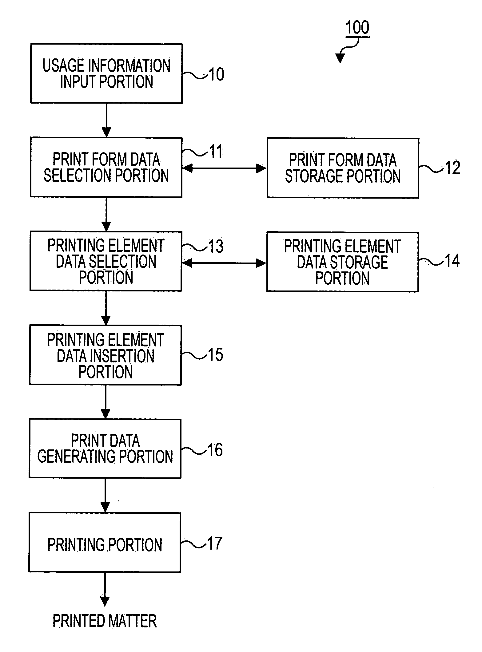
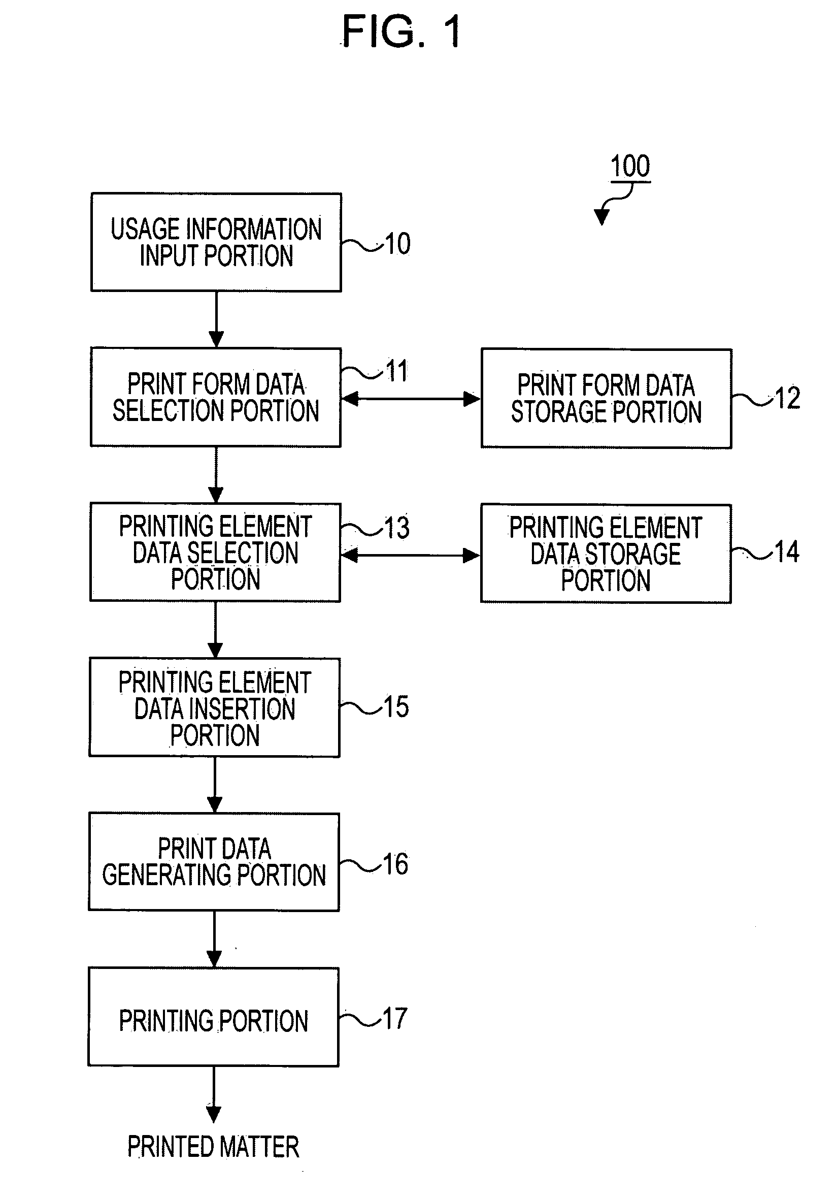
[0062]Hereinafter, a first embodiment of the invention will be described with reference to the accompanying drawings. FIG. 1 to FIG. 11 are views that show a first embodiment of a printer, a printing program and a printing method according to the first embodiment of the invention. First, the configuration of the printer according to the first embodiment of the invention will be described with reference to FIG. 1. FIG. 1 is a block diagram that shows the configuration of the printer 100 according to the first embodiment of the invention.

[0063]As shown in FIG. 1, the printer 100 includes a usage information input portion 10, a print form data selection portion 11, a print form data storage portion 12, a printing element data selection portion 13, and a printing element data storage portion 14. The usage information input portion 10 inputs usage information that indicates the usage of a printed matter. The print form data selection portion 11 randomly selects a piece of print form data...

second embodiment

[0121]Next, a second embodiment of the invention will be described with reference to the accompanying drawings. FIG. 12 to FIG. 23 are views that show a second embodiment of a printer, a printing program and a printing method according to the invention.

[0122]First, the configuration of the printer according to the second embodiment of the invention will be described with reference to FIG. 12. FIG. 12 is a block diagram that shows the configuration of a printer 300 according to the second embodiment of the invention. The present embodiment differs from the first embodiment in that, on the basis of the frequencies of nozzles used for print form data that are printed for a past predetermined period, the frequencies of use of nozzles in the predetermined period are recognized, and a piece of print form data used for printing is selected on the basis of the recognized content. In addition, the present embodiment also differs from the first embodiment in that each piece of print form data...


PUM


Abstract

A printer includes a print head in which nozzles that form an image by discharging ink are arranged in a plurality of lines. The printer prints out an image on the basis of print form data in which information of layout contents of printing elements that form the content of print is set according to the attribute of each printing element. The printer includes a print form data storage unit, a printing element data storage unit, a print form data selection unit, a printing element data selection unit, and a printing element data insertion unit.

Description

[0001]Priority is claimed under 35 U.S.C. § 119 from Japanese Patent Application No. JP 2007-043396 filed on Feb. 23, 2007, which is hereby incorporated by reference in its entirety.BACKGROUND[0002]1. Technical Field[0003]The present invention relates to a printer that prints out an image by discharging ink from nozzles, a printing program, and a printing method.[0004]2. Related Art[0005]For example, in an existing ink jet printer that prints out an image by discharging ink form nozzles, a process (which is called flushing, or the like) is performed to discharge ink from all the nozzles at a constant period of time during the printing process. In this manner, ink is prevented from clogging nozzles that are not used for printing. The above flushing technology is, for example, described as an ink jet recording apparatus in JP-A-2004-106470.[0006]The ink jet recording apparatus described in JP-A-2004-106470 is provided with a head movement driving portion that reciprocally moves a line...

Claims


Application Information

Patent Timeline
Patent Type & Authority Applications(United States)
IPC IPC(8): B41J2/015
CPCB41J2/16585G06K2215/0082G06K15/102B41J2202/21
Inventor SAKAI, HIROAKI
Owner SEIKO EPSON CORP
Learn More