
Golf club shaft

a golf club and shaft technology, applied in the field of golf club shafts, can solve the problems of deterioration and durability of shafts, and achieve the effect of enhancing durability

Inactive Publication Date: 2009-03-12
DUNLOP SPORTS CO LTD
View PDF3 Cites 20 Cited by
  • Summary
  • Abstract
  • Description
  • Claims
  • Application Information

AI Technical Summary

Benefits of technology

[0008]In a carbon shaft, a partial layer (a partial reinforced layer) can be provided partially in a longitudinal direction of the shaft in addition to a full length layer provided wholly in the longitudinal direction of the shaft. The partial layer can be provided in a tip portion of the shaft, a rear end of the shaft, a central portion of the shaft and the like, for example. It is possible to select a position, a length and a thickness of the partial layer and the like. By the partial layer, it is possible to enhance a degree of freedom of design in the shaft. The enhancement in the degree of freedom of design can contribute to an increase in a flight distance and an improvement in a hitting feeling.
[0009]In recent years, there is a tendency that a resilience coefficient of a golf club head is regulated. It has been hard to increase the flight distance depending on the characteristic of the head. For this reason, it has been required to increase the flight distance depending on the characteristic of the shaft. A lightweight shaft contributes to the increase in the flight distance. Since the partial layer can selectively reinforce a portion having a low strength, it is useful for a reduction in the weight of the shaft.
[0011]It is an object of the present invention to provide a golf club shaft which has a partial layer and can enhance a durability.
[0016]In the golf club shaft according to the present invention in which the partial sheet is distributed in the longitudinal direction of the shaft, the end of the partial sheet is distributed in the longitudinal direction of the shaft. In the shaft, a stress acting on the end of the partial sheet is distributed. Therefore, a durability can be enhanced.

Problems solved by technology

However, it has been found that a durability of the shaft is apt to be deteriorated due to the presence of the partial layer.
Furthermore, it has been found that the durability of the shaft is particularly apt to be deteriorated if a large number of partial layers are provided.

Method used


Image

  • Golf club shaft
  • Golf club shaft
  • Golf club shaft

Examples


example 1

[0104]In the same manner as the shaft 6 according to the embodiment, there was obtained a shaft shown in the developed view of FIG. 3 (the view showing a structure of a sheet). For a manufacturing method, a sheet winding process was employed. A full length L of the shaft was set to be 1168 mm. TR350C-100S was used for a sheet a1, HRX350C-075S was used for a sheet a2, HRX350C-075S was used for a sheet a3, MR350C-100S was used for a sheet a4, 805S-3 was used for a sheet a5, MR350C-100S was used for a sheet a6, 805S-3 was used for a sheet a7, MR350C-100S was used for a sheet a8, MR350C-100S was used for a sheet a9, 805S-3 was used for a sheet a10, MR350C-100S was used for a sheet a11, and TR350C-100S was used for a sheet a12. A total of the sheets a2 and a3 was set to be three plies. The other sheets were set to be one ply, respectively. A portion constituting an end of a partial sheet has the number of plies which is smaller than one. A weight of the shaft was 47 g. In the example 1, ...

example 2

[0105]A shaft according to an example 2 was obtained in the same manner as in the example 1 except for the developed view of the shaft (the view showing a structure of a sheet) illustrated in FIG. 5. TR350C-100S was used for a sheet b1, HRX350C-075S was used for a sheet b2, HRX350C-075S was used for a sheet b3, MR350C-100S was used for a sheet b4, 805S-3 was used for a sheet b5, MR350C-100S was used for a sheet b6, 805S-3 was used for a sheet b7, MR350C-100S was used for a sheet b8, MR350C-100S was used for a sheet b9, 805S-3 was used for a sheet b10, MR350C-100S was used for a sheet b11, and TR350C-100S was used for a sheet b12. A total of the sheets b2 and b3 was set to be three plies. The other sheets were set to be one ply, respectively. A portion constituting an end of a partial sheet has the number of plies which is smaller than one. A weight of the shaft was 43 g. Fiber orientation angles of the sheets b1 to b12 are shown in FIG. 5. The specification and evaluation result of ...

example 3

[0106]A shaft according to an example 3 was obtained in the same manner as in the example 1 except for the developed view of the shaft (the view showing a structure of a sheet) illustrated in FIG. 6. TR350C-100S was used for a sheet c1, HRX350C-075S was used for a sheet c2, HRX350C-075S was used for a sheet c3, MR350C-100S was used for a sheet c4, 805S-3 was used for a sheet c5, MR350C-100S was used for a sheet c6, 805S-3 was used for a sheet c7, MR350C-100S was used for a sheet c8, MR350C-100S was used for a sheet c9, 805S-3 was used for a sheet c10, MR350C-100S was used for a sheet c11, and TR350C-100S was used for a sheet c12. A total of the sheets c2 and c3 was set to be three plies. The other sheets were set to be one ply, respectively. A portion constituting an end of a partial sheet has the number of plies which is smaller than one. A weight of the shaft was 42 g. Fiber orientation angles of the sheets c1 to c12 are shown in FIG. 6. The specification and evaluation result of ...


PUM


Abstract

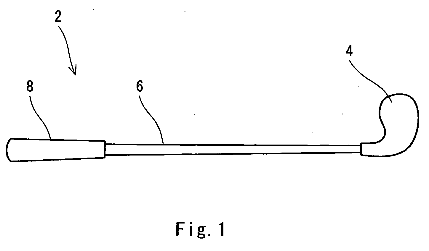
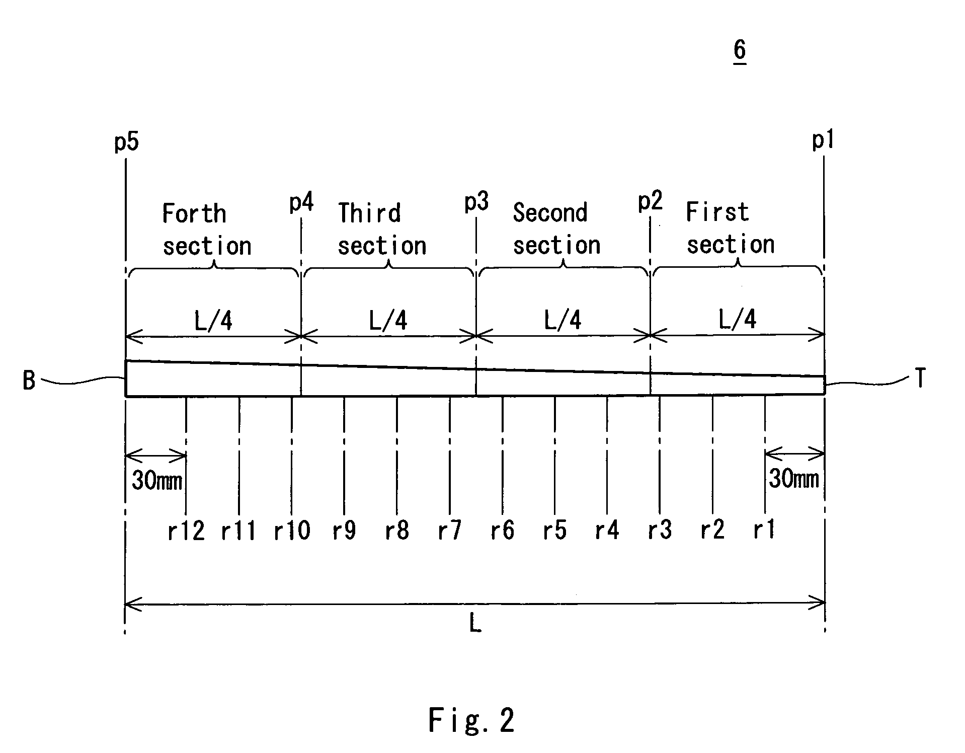
A shaft 6 is formed by a prepreg sheet. The sheet of the shaft 6 includes full length sheets (a2), (a3), (a8) and (a11) provided wholly in a longitudinal direction of the shaft, and partial sheets (a1), (a4), (a5), (a6), (a7), (a9), (a10) and (a12) provided partially in the longitudinal direction of the shaft. The number of the full length sheets is equal to or greater than two. The number of the partial sheets is equal to or greater than four. Each of the partial sheets has an end. When four sections obtained by dividing the shaft into four equal parts in the longitudinal direction are set to be first, second, third and fourth sections from a tip end side in order, the total number of ends positioned in the first section is represented as (N1), the total number of ends positioned in the second section is represented as (N2), the total number of ends positioned in the third section is represented as (N3), and the total number of ends positioned in the fourth section is represented as (N4), all of (N1), (N2), (N3) and (N4) are equal to or greater than one.

Description

[0001]This application claims priority on Patent Application No. 2007-236779 filed in JAPAN on Sep. 12, 2007, the entire contents of which are hereby incorporated by reference.BACKGROUND OF THE INVENTION[0002]1. Field of the Invention[0003]The present invention relates to a golf club shaft.[0004]2. Description of the Related Art[0005]As a golf club shaft, so-called steel and carbon shafts have been known. The carbon shaft is constituted by CFRP (carbon fiber reinforced plastic).[0006]Most of the carbon shafts are manufactured by a so-called sheet winding process. In the sheet winding process, a prepreg sheet including a fiber and a matrix resin is used. In the process, a sheet formed of prepreg is wound around a metallic core member and the matrix resin is then cured by heating, and the core member is pulled out after the curing. By the process, there is formed a shaft which is obtained by winding and curing the prepreg sheet.[0007]Japanese Laid-Open Patent Publication No. 2003-2448...

Claims


Application Information

Patent Timeline
Patent Type & Authority Applications(United States)
IPC IPC(8): A63B53/10A63B102/32
CPCA63B53/10A63B2209/026A63B2209/023A63B59/0014A63B60/10A63B60/06A63B60/08
Inventor KUMAMOTO, TOMIO
Owner DUNLOP SPORTS CO LTD
Learn More