Pedal arrangement for operating a clutch

a technology of a clutch and a pedal, which is applied in the direction of mechanical control devices, manual control with a single controlling member, instruments, etc., can solve the problems of non-linear force-displacement ratio, complex configuration of the art device intended to solve the problem, and the force needed to be applied to the pedal in order to operate the clutch, etc., to achieve simple mechanical configuration, simple and robust configuration, and comparatively simple mechanical configuration

Inactive Publication Date: 2009-03-19
LUK LAMELLEN & KUPPLUNGSBAU BETEILIGUNGS KG
View PDF14 Cites 13 Cited by
  • Summary
  • Abstract
  • Description
  • Claims
  • Application Information

AI Technical Summary

Benefits of technology

[0011]The pedal arrangement preferably includes another groove, which has the same shape as the first groove, wherein the grooves are respectively disposed on opposite sides of the pedal lever. Thus, on the opposite side of the pedal lever means that the grooves are disposed on the side of the pedal lever with respect to the movement direction of the pedal lever. It is advantageous, in particular, that the grooves are substantially disposed in parallel to one another or parallel to the movement direction of the pedal lever. That, in turn, has the advantage that the mechanical configuration is comparatively simple.
[0012]It is furthermore advantageous that the pivot axis is disposed on a pedal support element and that the grooves also are configured in the pedal support element. That has the advantage of a particularly simple and robust configuration. The pedal support element can be a portion of the vehicle body or it can be a pedal receiver support element that is mounted to the vehicle body. Preferably, the pedal support element is a substantially U-shaped piece of sheet metal, in which the grooves are configured in the lateral arms of the U-shaped support element.
[0013]A push rod for actuating the clutch is preferably mounted to the operating member, wherein the mount is preferably a link mount. In particular, in conjunction with providing the operation member as a pin, a simple mechanical configuration is achieved in that manner.
[0014]The groove preferably is wave shaped. Thus, wave shaped means that the groove is of undulating, generally S-shaped form and is configured so that the radial distance of the operating member in the slide bearing surface from the pivot axis is initially increased or reduced, when actuating the pedal lever in one direction, and subsequently reduced again or increased upon further actuation of the pedal lever in the same direction. That means that while the pedal lever is actuated in one direction the position of the operating member moves in different directions along the slot in the pedal lever. It is particularly advantageous that upon actuation of the pedal lever by a user the operating member initially moves radially toward the pivot axis, and subsequently upon further actuation of the pedal lever in the same direction the operating member moves radially away from the pivot axis again. It thereby facilitates a reduction of the load drop that is typical for motor vehicle clutches. Wave form preferably also means that the shape of the groove includes at least two oppositely oriented curvatures.
[0015]The groove is preferably configured so that a force that is a function of the angular position of the pedal lever, and which is to be imparted to the pedal lever for actuating the clutch, is smoothed or substantially more uniform over an angular position movement range of the pedal lever. Substantially more uniform means that at angular positions of the pedal lever at which a particularly high actuation force normally has to be imparted when utilizing the known clutch pedal arrangements, that actuation force and the range of actuation forces over an adjacent angular range are reduced in the pedal arrangement in accordance with the present invention. In that way, when actuating the clutch, the maximum forces in the force-displacement diagram for the pedal arrangement in accordance with the present invention are reduced, and, furthermore, the pedal load drop after a maximum force is reduced.
[0016]Preferably, it is provided that the operating member includes a first pin and a second pin, which pins are in fixed positions relative to one another. Thus, the push rod is preferably connected to the pin that is radially closest to the pivot axis. The first pin and the second pin are preferably supported so that they are jointly movable along a slot and in a substantially radial direction relative to the pivot axis. The push rod is thus supported radially further inwardly toward the pedal arm rotation axis, so that the push rod completes the radial direction movement defined by the groove, but so that it performs a smaller movement in a tangential direction because of the smaller distance to the pedal arm rotation axis. In that way a greater variability of the path relationship of the pedal path to the reduction ratio relative to the displacement of the push rod can be implemented.

Problems solved by technology

That pedal arrangement, however, has the disadvantage that the force needed to be applied to the pedal in order to operate the clutch is substantially directly proportional to the force that is required at the clutch to operate the clutch.
That is disadvantageous, because the clutches that are typically used in motor vehicles have a non-linear force-displacement ratio when actuated by a user.
That result is generally referred to as pedal load drop-off and is perceived as unpleasant by users, and thus constitutes a disadvantage.
State-of-the-art devices that are intended to solve that problem have a complex configuration.
A complex configuration, however, is also undesirable for reliability and cost reasons.

Method used


Image

  • Pedal arrangement for operating a clutch
  • Pedal arrangement for operating a clutch
  • Pedal arrangement for operating a clutch

Examples


first embodiment

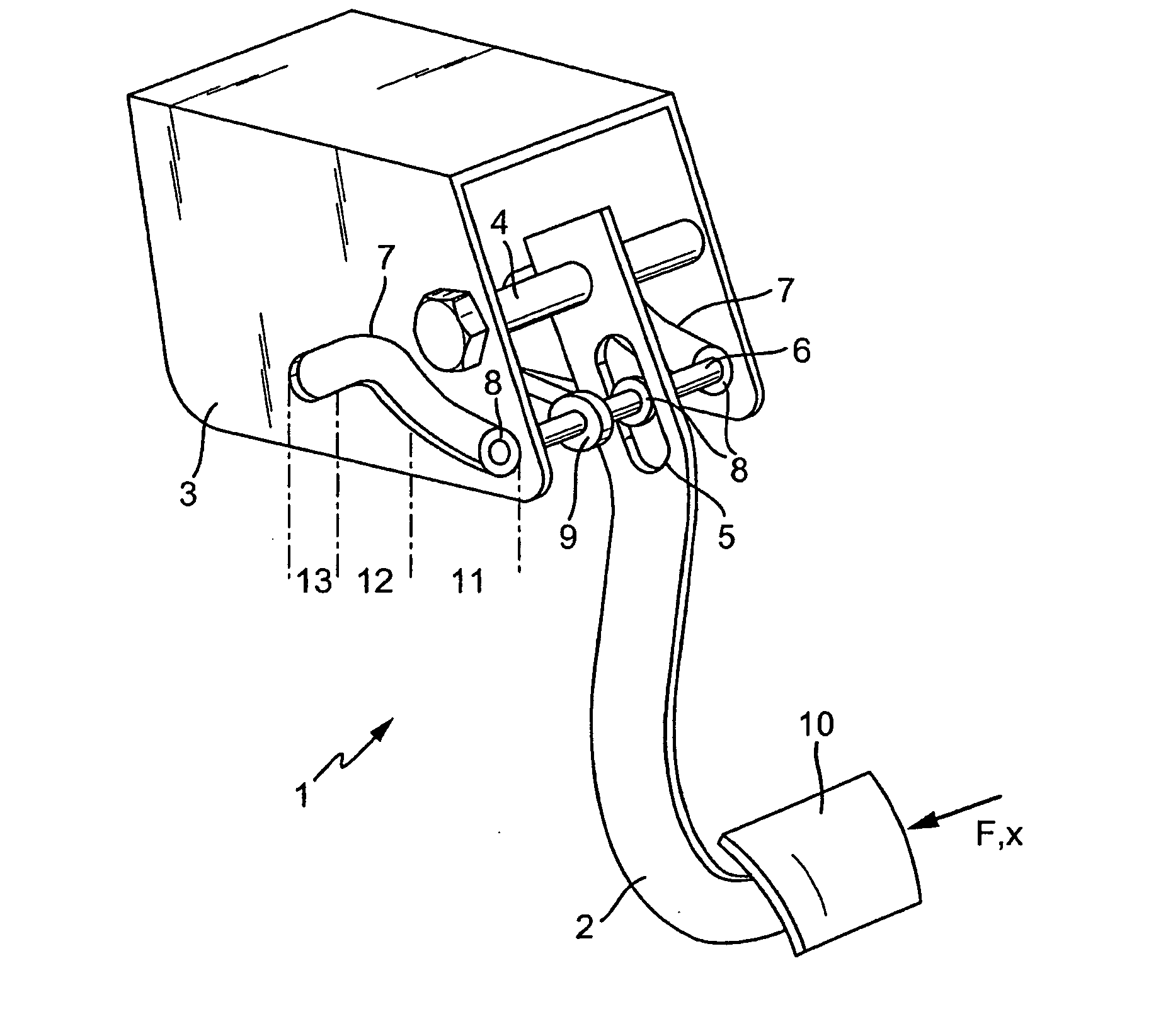
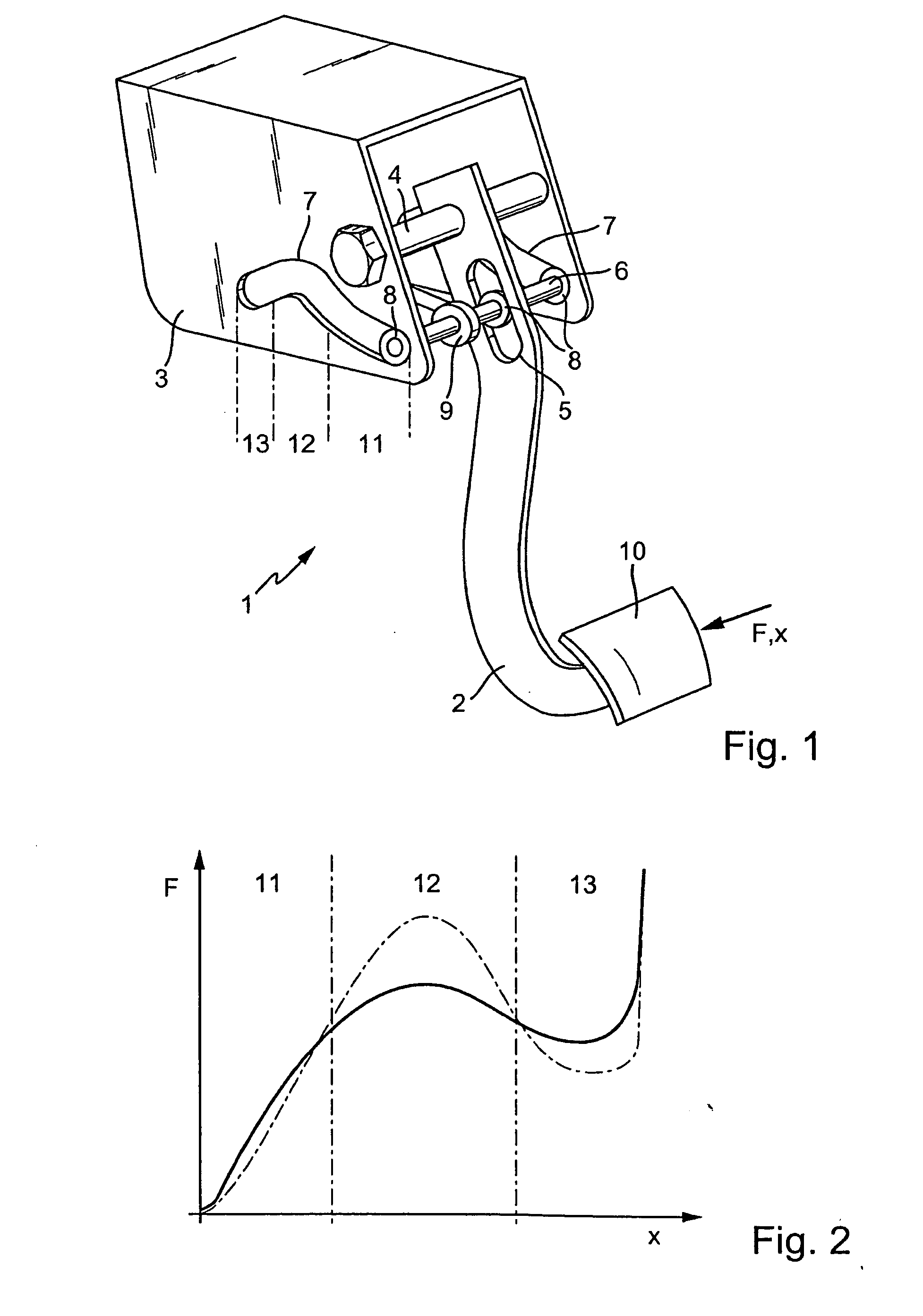
[0021]FIG. 1 shows a perspective view of a pedal arrangement 1 in accordance with the present invention. A pedal lever 2 is pivotably supported in a U-shaped support element 3 on a pivot axis 4 that is supported by two lateral arms of the support element 3. The pedal lever 2 is carried by the pivot axis 4. The pivot axis 4 thus forms a hinge for the pedal lever 2. The pedal lever 2 includes a slide bearing surface 5 that is configured as an elongated opening or slot. The slide bearing surface 5 is oriented in a radial direction relative to the pivot axis 4.

[0022]An operating member 6 in the form of a pin is rotatably carried in the slide bearing surface or slot 5. The operating member 6 is also supported in two opposed grooves 7 that are formed in respective lateral arms of the support element 3. The support of the operating member 6 in the slide bearing surface or slot 5 and the in grooves 7 is effected by bearings 8. A push rod 9 is carried by the operating member 6, wherein the p...

second embodiment

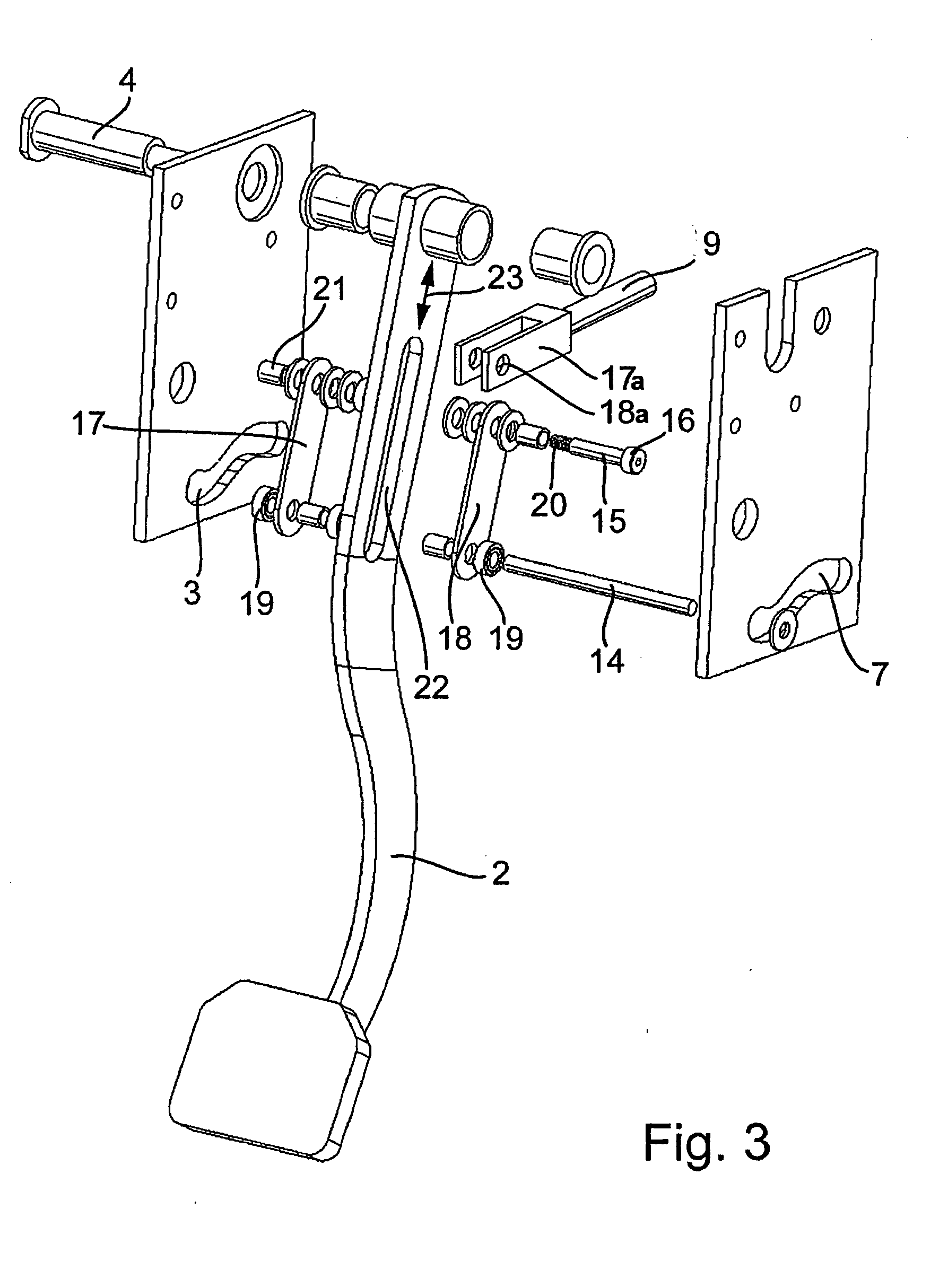
[0028]FIG. 3 shows an exploded view of the present invention. In the embodiments shown in FIGS. 1 and 3 identical components are identified by the same reference numerals, and they are therefore not described again. In the embodiment in accordance with FIG. 3, the operating member is formed as two components and includes a first pin 14 and a second pin 15. The first pin 14 interacts with the groove 7, while the second pin 15 is used for connection with the push rod 9. The second pin 15 includes a pin head 16 and a threaded end 20, onto which a safety nut 21 is threaded. The pins 14 and 15 are connected by connecting links 17 and 18, which are disposed on respective opposite sides of the pedal lever 2. The push rod 9 is connected to the second pin 15 by a fork 17a. For that purpose, the fork 17a includes two arms that each includes a bore 18a through which the second pin 15 is inserted. The first pin 14 is provided with support rings 19 on both ends, which can be plastic rings, ball ...


PUM


Abstract

A clutch pedal arrangement for operating a clutch to provide a variable pedal force transmission ratio. The pedal arrangement includes a pivotally-supported pedal lever that pivots about a pivot axis. An operating member that is in operative engagement with the clutch is connected to the pedal lever for movement along a slotted slide bearing surface carried by the pedal lever to allow radial movement of the operating member relative to the pivot axis. The operating member is guided in and supported by the slide bearing surface of the pedal lever and is movable along at least one curved groove carried by a pedal support member.

Description

BACKGROUND OF THE INVENTION[0001]1. Field of the Invention[0002]The present invention relates to a pedal arrangement, in particular to a clutch pedal arrangement for operating a clutch with a variable pedal force transmission ratio. The pedal arrangement includes a pedal lever that is pivotally supported at a pivot axis, and an operating member that is carried by the pedal lever within a slotted slide bearing surface. The operating member is configured to be in operative engagement with the clutch, wherein the slide bearing surface is disposed at the pedal lever so that a radial movement of the operating member is facilitated with reference to the pivot axis.[0003]2. Description of the Related Art[0004]It is known in the art to actuate clutches with a clutch pedal carried by a lever. A control rod or a pull cable is connected to the pedal lever and to the clutch to operate the clutch. That pedal arrangement, however, has the disadvantage that the force needed to be applied to the pe...

Claims


Application Information

Patent Timeline
Patent Type & Authority Applications(United States)
IPC IPC(8): G05G1/30
CPCG05G1/30Y10T74/20528G05G7/04G05G5/03
Inventor LAUDERBAUGH, STEVE
Owner LUK LAMELLEN & KUPPLUNGSBAU BETEILIGUNGS KG
Why Eureka
Try Eureka