Apparatus and process for formation of laterally directed fluid jets

a technology of fluid jets and apparatuses, which is applied in the direction of grinding machine components, coatings, manufacturing tools, etc., can solve the problems of unsuitable for processing many types of workpieces, unsuitable for remote locations or confined spaces, and aircraft components may provide minimal clearan

Active Publication Date: 2009-03-19
FLOW INT
View PDF30 Cites 46 Cited by
  • Summary
  • Abstract
  • Description
  • Claims
  • Application Information

AI Technical Summary

Benefits of technology

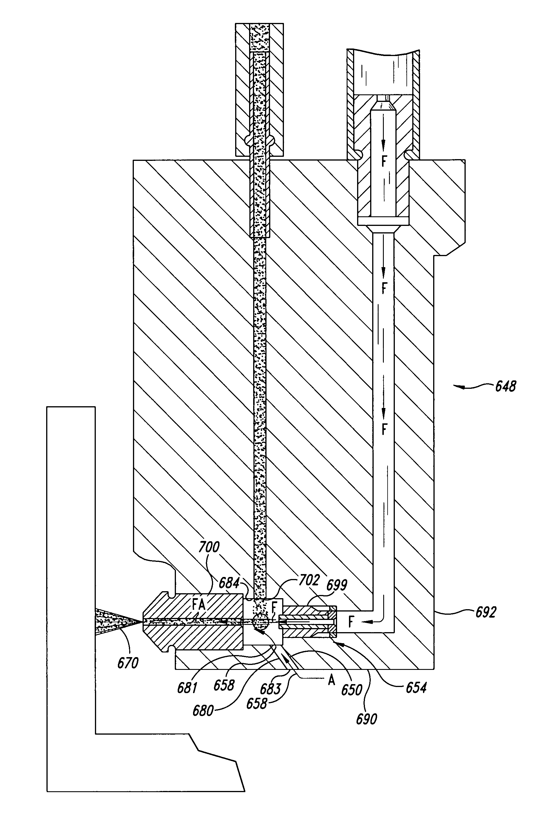
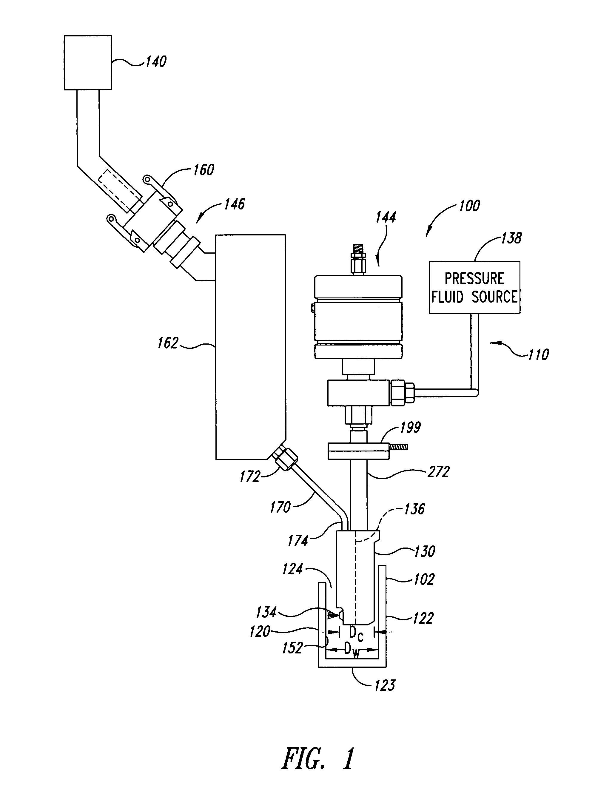
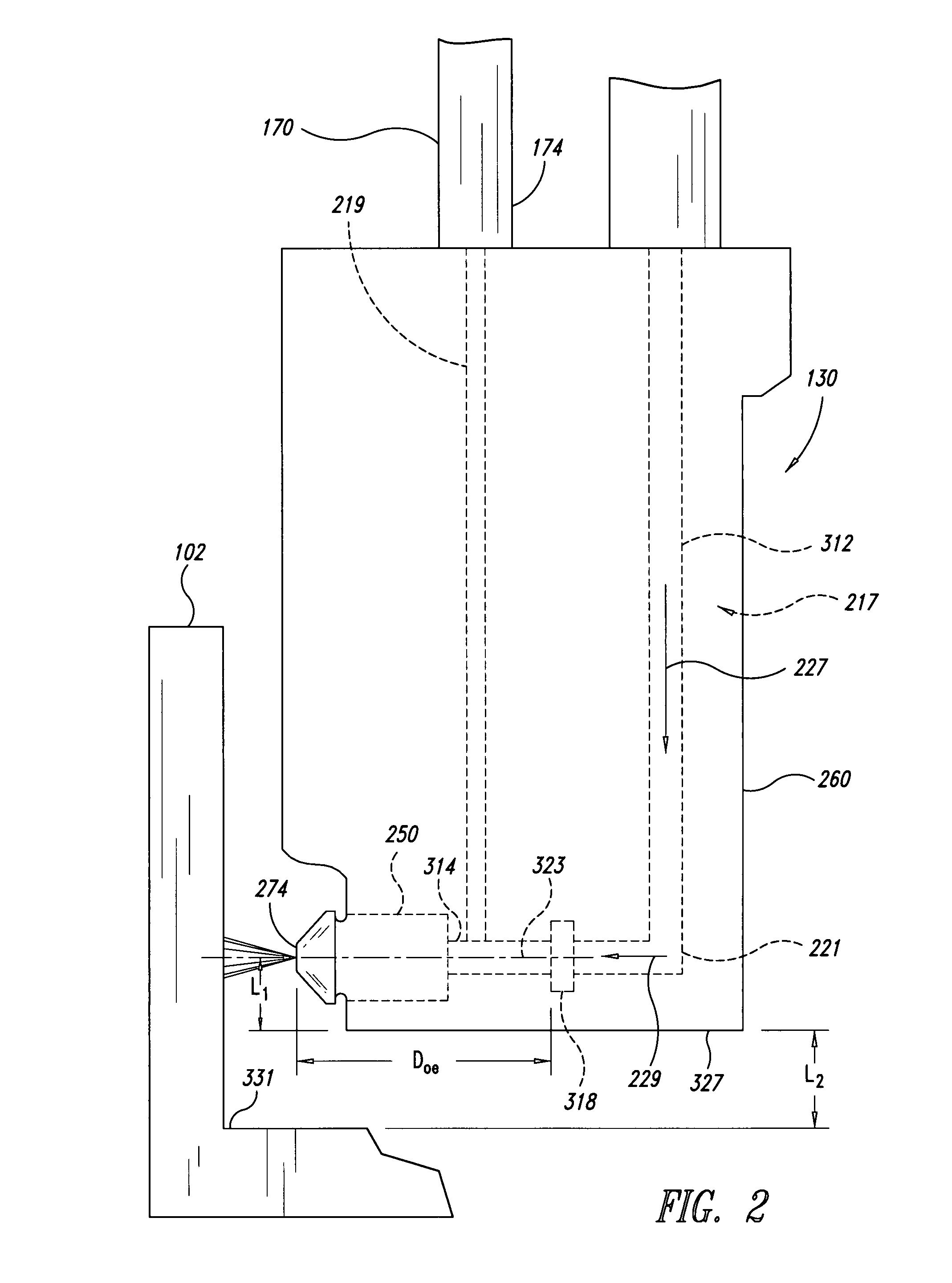
[0008]Some embodiments disclosed herein include the development of a fluid jet delivery system having a nozzle system dimensioned to fit into relatively small spaces. For example, a low-profile nozzle system of a fluid jet delivery system can be navigated through narrow spaces to access a target region, even remote interior regions of a workpiece. Low-profile nozzle systems can fit within various features including, without limitation, apertures, bores, channels, gaps, chambers, cavities, and the like, as well as other features that may provide access to a target site. During a single processing sequence, the nozzle system can pass through any number of features with varying sizes and geometries.

Problems solved by technology

Fluid jet systems often have straight nozzle systems that require significant operating clearance around the target workpiece and, consequently, may be unsuitable for processing workpieces in remote locations or within confined spaces.
For example, nozzle systems are often slender and have large axial lengths rendering them unsuitable for processing many types of workpieces.
Unfortunately, numerous locations of aircraft components may provide minimal amounts of clearance.
It may be difficult or impossible to adequately process these areas due to the large overall axial length of conventional fluid jet nozzle systems.
Conventional nozzles have axial lengths that are greater than 1.5 inches and, consequently, are unsuitable for use in such tight spaces.
Other types of workpieces may likewise have features that cannot be adequately accessed with traditional fluid jet systems.

Method used


Image

  • Apparatus and process for formation of laterally directed fluid jets
  • Apparatus and process for formation of laterally directed fluid jets
  • Apparatus and process for formation of laterally directed fluid jets

Examples


Embodiment Construction

[0034]The following description relates to processes and systems for generating and delivering fluid jets suitable for cleaning, abrading, cutting, milling, or otherwise processing workpieces. The fluid jets can be used to conveniently process a wide range of features having different shapes, sizes, and access paths. For example, a fluid jet delivery system can have a nozzle system for delivery through deep or narrow openings, channels, or holes, as well as other difficult to access locations, in addition to easily accessible locations (e.g., an exterior surface of a workpiece). Fluid jet delivery systems with low-profile nozzle systems are disclosed in the context of processing regions of workpieces with minimal clearances because they have particular utility in this context. For example, low-profile nozzle systems can be navigated into and through relatively small spaces in order to access and then process remote interior regions of the workpiece.

[0035]Unless the context requires ...


PUM

PropertyMeasurementUnit
angleaaaaaaaaaa
angleaaaaaaaaaa
distanceaaaaaaaaaa

Abstract

A processing apparatus is provided to process a workpiece. The processing apparatus can have a low-profile nozzle system capable of navigating through spaces in order to process target regions with relatively small clearances. A fluid jet outputted from the nozzle system is used to cut, mill, or otherwise process the target region of the workpiece.

Description

BACKGROUND OF THE INVENTION[0001]1. Field of the Invention[0002]The present invention relates generally to processes and apparatuses for generating fluid jets, and in particular, processes and apparatuses for generating laterally directed high-pressure fluid jets.[0003]2. Description of the Related Art[0004]Conventional fluid jet systems have been used to clean, cut, or otherwise process workpieces by pressurizing fluid and then delivering the pressurized fluid against workpieces. Fluid jet systems often have straight nozzle systems that require significant operating clearance around the target workpiece and, consequently, may be unsuitable for processing workpieces in remote locations or within confined spaces.[0005]For example, nozzle systems are often slender and have large axial lengths rendering them unsuitable for processing many types of workpieces. A conventional nozzle system may have a long straight feed tube, a cutting head and a long straight mixing tube aligned with and...

Claims


Application Information

Patent Timeline
Patent Type & Authority Applications(United States)
IPC IPC(8): B26F1/26B26F3/00
CPCB24C3/325B24B41/00B24C5/02B05B7/149Y10T83/0591
Inventor HASHISH, MOHAMEDCRAIGEN, STEVESCHUMAN, BRUCEULLRICH, ECKHARDTOROVA, JENO
Owner FLOW INT
Why Eureka
Try Eureka