Window pallet and method of use thereof

a window frame and pallet technology, applied in the field of windows, can solve the problems of time-consuming and cost-inefficient use of windows, damage to the fins, increase the labor cost of loading and unloading the windows of the past, etc., and achieve the effects of convenient loading and unloading of windows, safe transportation or storage, and efficient storag

Inactive Publication Date: 2009-03-19
AMCOR PACKAGING DISTRIBUTION
View PDF35 Cites 13 Cited by
  • Summary
  • Abstract
  • Description
  • Claims
  • Application Information

AI Technical Summary

Benefits of technology

[0011]The present invention is directed to a pallet for holding fragile items such as, for example, window frames, glass windows, glass doors, and the like during storage and transportation of those items. The pallet includes movable sides with slots configured to receive a fin of a window frame loaded onto the pallet. One of the movable sides of the pallet is fixed by a plurality of straps in a position that facilitates loading and unloading of the window frames by a single person. When secured on the pallet within the slots and between the movable sides of the pallet, the window frames can be safely transported or stored even when pallets are stacked on top of one another. The movable sides of the pallet can be positioned in a collapsed or closed position that allows the pallet to be efficiently stored when not in use.

Problems solved by technology

Prior pallets have various disadvantages that make their use time consuming and cost-inefficient.
Since the fin is structurally weaker than the frame itself, placement of window frames with their fins directly on the wooden surface of the pallets such that the weight of the frame is supported by the fin could result in damage to the fins during storage or transportation.
The use of two people to load and unload pallets significantly increases the labor costs to load and unload the pallets of the past.
Another disadvantage of the prior pallets is that the plastic sides of the pallets cannot be affixed to the window frames without a fastener, such as a screw or a staple, that is driven through the frame itself.
The use of a large number of intermediate blocks and screws to attach window frames to the movable sides of the pallets significantly increases the amount of time and labor required to load the window frames onto the pallet and the amount of time and labor required to unload the window frames from the pallet.
As a result, the use of such pallets incurred significant costs.

Method used


Image

  • Window pallet and method of use thereof
  • Window pallet and method of use thereof
  • Window pallet and method of use thereof

Examples


Embodiment Construction

[0025]Reference will now be made in detail to the preferred embodiments, examples of which are illustrated in the accompanying drawings. Wherever possible, the same reference numbers will be used throughout the drawings to refer to the same or like parts.

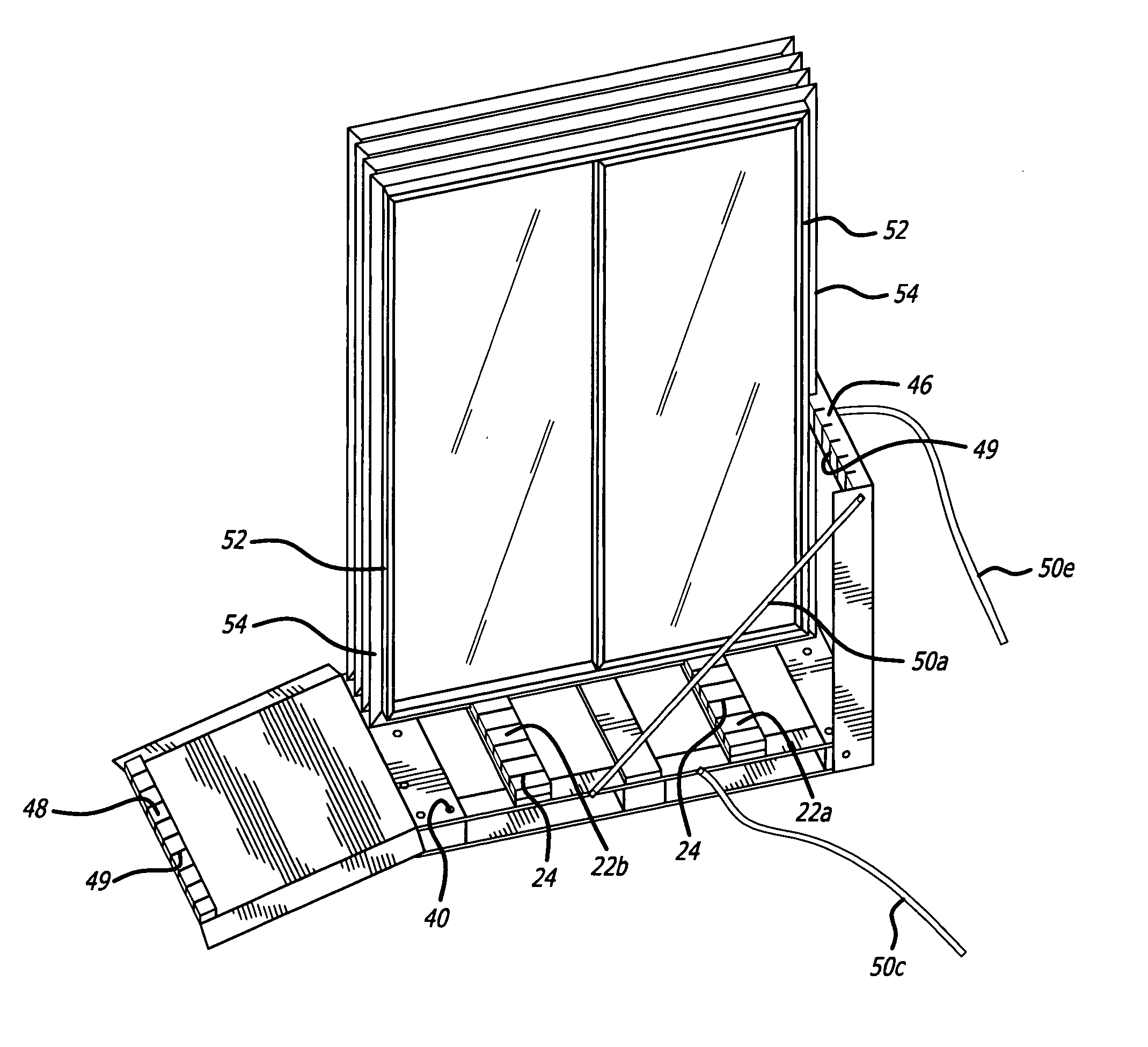
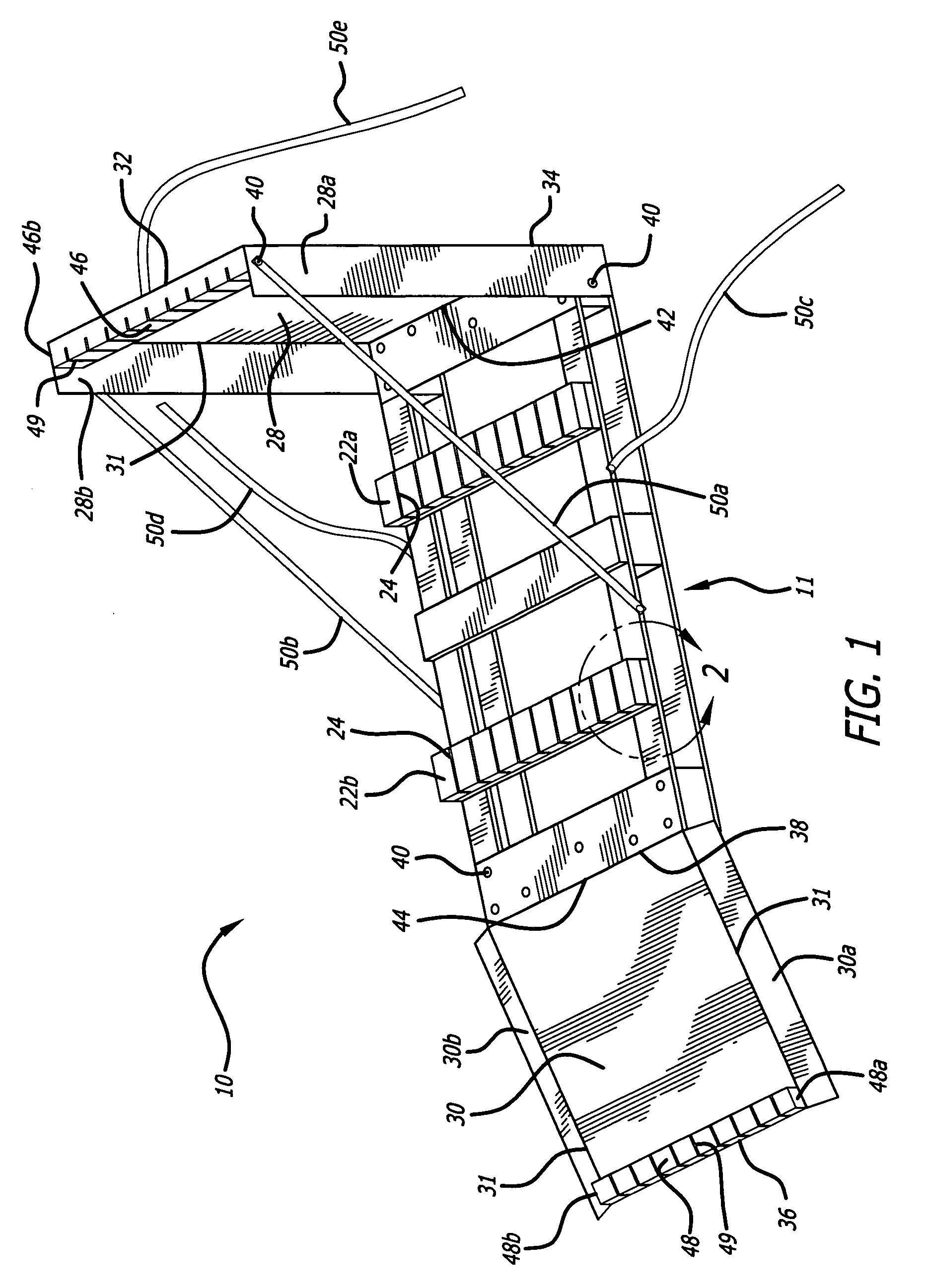
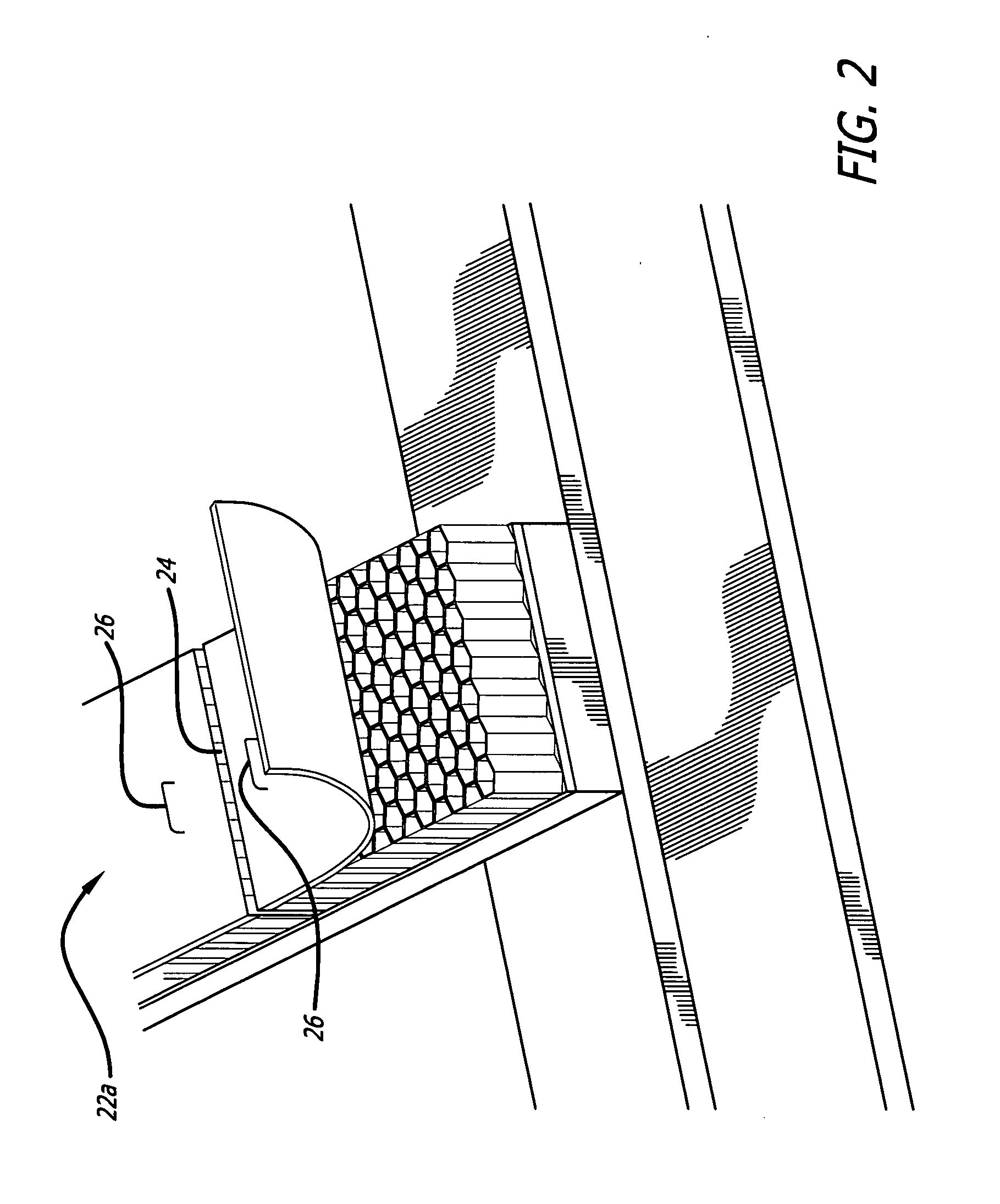
[0026]In a preferred embodiment, a pallet for holding windows protects three sides of a window frame during storage and transportation. The pallet includes movable sides having slots configured to receive a fin of a window frame loaded onto the pallet. A movable side of the pallet is fixed by a plurality of straps in a stationary position, allowing easy loading and unloading of the window frames onto or from the pallet by a single person. When loaded on the pallet and into the slots of the side fixed by straps, the window frames are in a secure upright position and do not need to be manually held up to prevent from falling. When window frames are secured on the pallet within the slots of and between both movable sides, the window fr...


PUM


Abstract

A pallet for holding at least one window frame includes a base and movable sides pivotally attached to the base. The movable sides are positionable to be substantially perpendicular to the base and are configured to hold the window frame. Connectors attached to the base and the movable sides, respectively, prevent the first and second movable sides from moving away from each other. A method for using the pallet is also disclosed.

Description

BACKGROUND[0001]1. Field of the Invention[0002]The present invention relates generally to pallets used for loading, holding, storing, and transporting commercial products, and more specifically, to a pallet for storing and transporting fragile items such as window frames.[0003]2. Description of the Related Art[0004]Conventional pallets are platforms used to hold and transport cargo loads of various types. The structure of a conventional pallet typically includes an upper portion and a lower portion separated by support blocks. The cargo loaded pallets are typically moved around by forklifts and pallet jacks.[0005]Various pallets have been used to transport window frames. A typical pallet may include a base and two movable sides. The base is usually made of wood and the movable sides are usually made of plastic. After a window frame is placed onto a pallet, the two movable sides are brought into vertical positions and secured to the loaded window frames. Prior pallets have various di...

Claims


Application Information

Patent Timeline
Patent Type & Authority Applications(United States)
IPC IPC(8): B65D19/38
CPCB65D19/44B65D2519/00875B65D2519/00024B65D2519/00029B65D2519/00034B65D2519/00059B65D2519/00064B65D2519/00069B65D2519/00174B65D2519/00273B65D2519/00293B65D2519/00333B65D2519/00502B65D2519/00507B65D2519/00572B65D2519/00656B65D2519/00805B65D2519/00815B65D2519/0082B65D85/48
Inventor PONTO, LEANNA L.
Owner AMCOR PACKAGING DISTRIBUTION
Why Eureka
Try Eureka