Three Dimensional Photo Voltaic Modules In An Energy Reception Panel

a photo voltaic module and energy reception technology, applied in photovoltaic supports, pv power plants, lighting and heating apparatus, etc., can solve the problems of reducing limiting the amount of surface area, and affecting the efficiency of absorption of energy, so as to reduce the amount of generated electricity, increase the absorption of radiant energy, and eliminate the effect of “flatness”

Active Publication Date: 2009-03-19
DAME CASEY
View PDF27 Cites 11 Cited by
  • Summary
  • Abstract
  • Description
  • Claims
  • Application Information

AI Technical Summary

Benefits of technology

[0008]The Present Invention overcomes the disadvantages in the currently-used devices by providing an apparatus geared towards, inter alia, the increased absorption of radiant energy from an energy source. In turn, the Present Invention allows for a greater amount of electricity to be generated. The Present Invention achieves this by, inter alia, eliminating the “flatness” of the present devices and provides a three dimensional absorption means. As a result, not only is the potentially absorbable surface area increased (while retaining the same length and width dimensions) vis-à-vis currently-used devices, but the Present Invention allows for the direct exposure with the light source for a much greater amount of time than currently-used devices.

Problems solved by technology

As a result of the static physical disposition of the energy receiving cells, efficiency of absorption of energy suffers as the energy source moves above the energy receiving panels, i.e., as the sun rotates from east to west above the energy receiving panels.
Further, the “flatness,” or planar nature, of the energy receiving cells limits the amount of surface area that is directly exposed to the energy source at any given point in time.
Consequently, when the efficiency of absorption of the energy receiving cells suffers, coupled with a less than optimum time of direct exposition to radiant energy, the amount of generated electricity is reduced.
Thus, the use of such energy receiving panels for the generation of electricity has been mainly limited by the poor efficiency and high exploitation costs of the energy receiving cells, as well as the reduced utility of the surface area due to the “flatness” of the energy receiving cells.

Method used


Image

  • Three Dimensional Photo Voltaic Modules In An Energy Reception Panel
  • Three Dimensional Photo Voltaic Modules In An Energy Reception Panel
  • Three Dimensional Photo Voltaic Modules In An Energy Reception Panel

Examples


Embodiment Construction

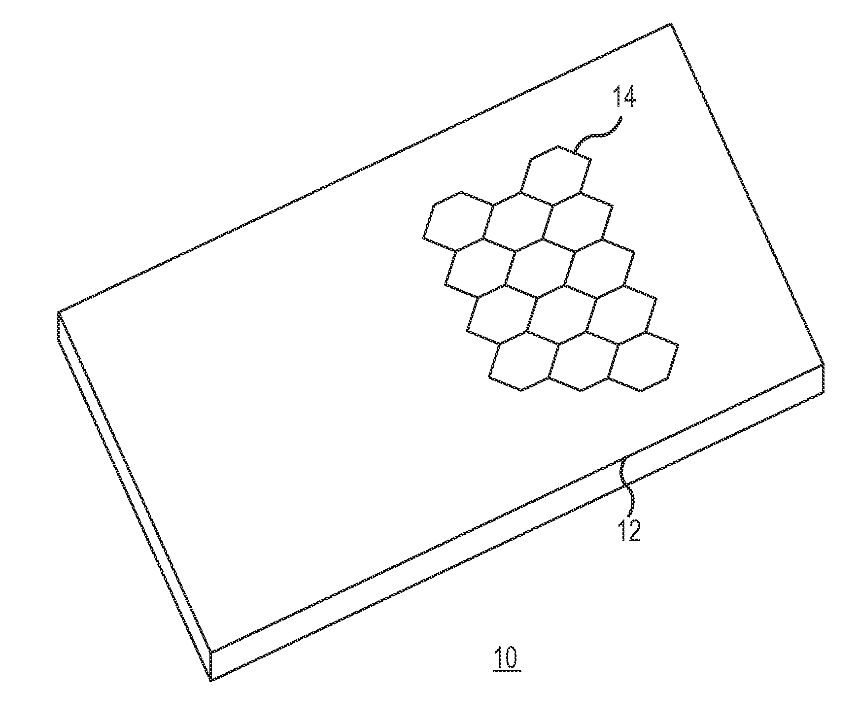
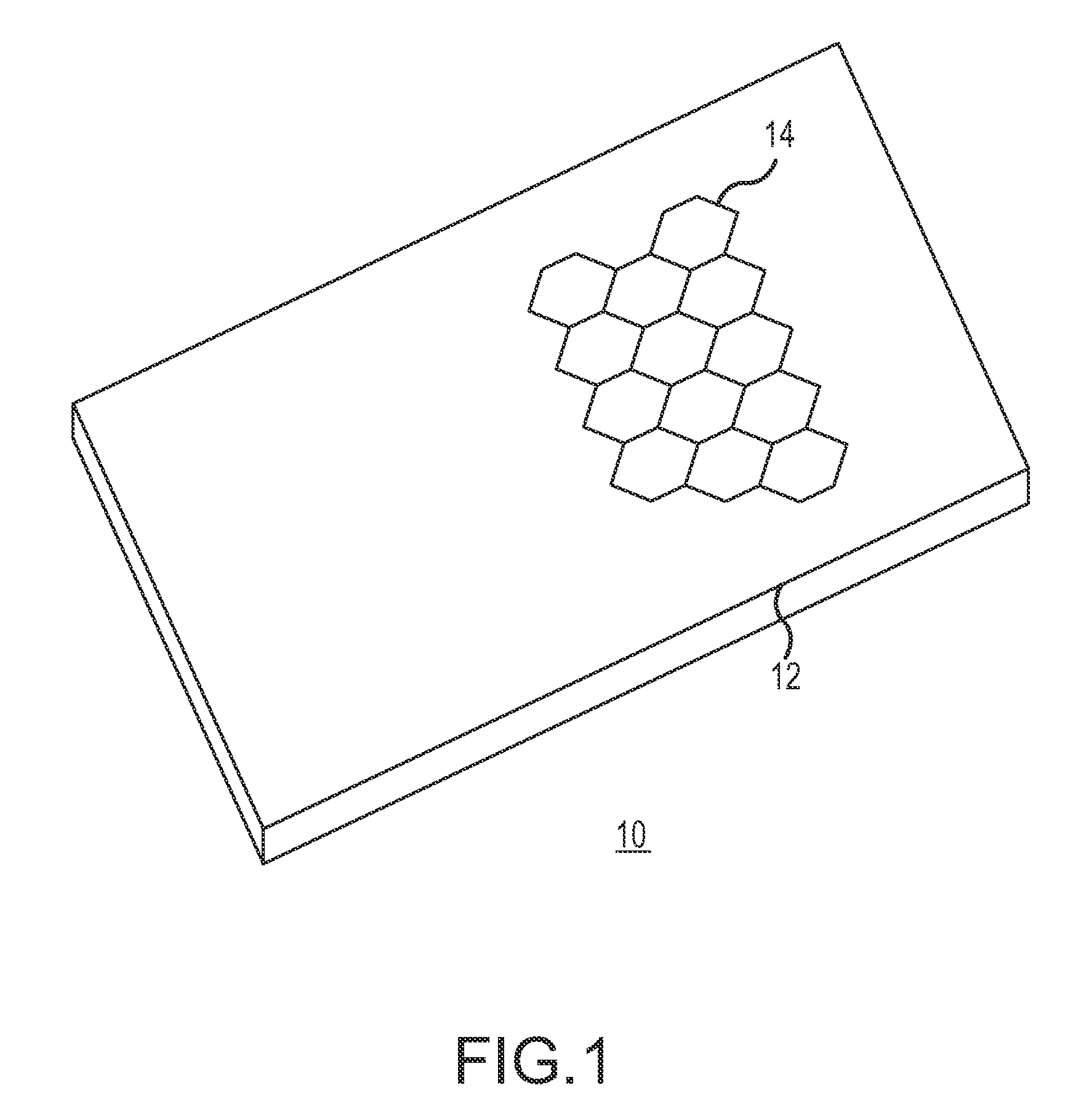
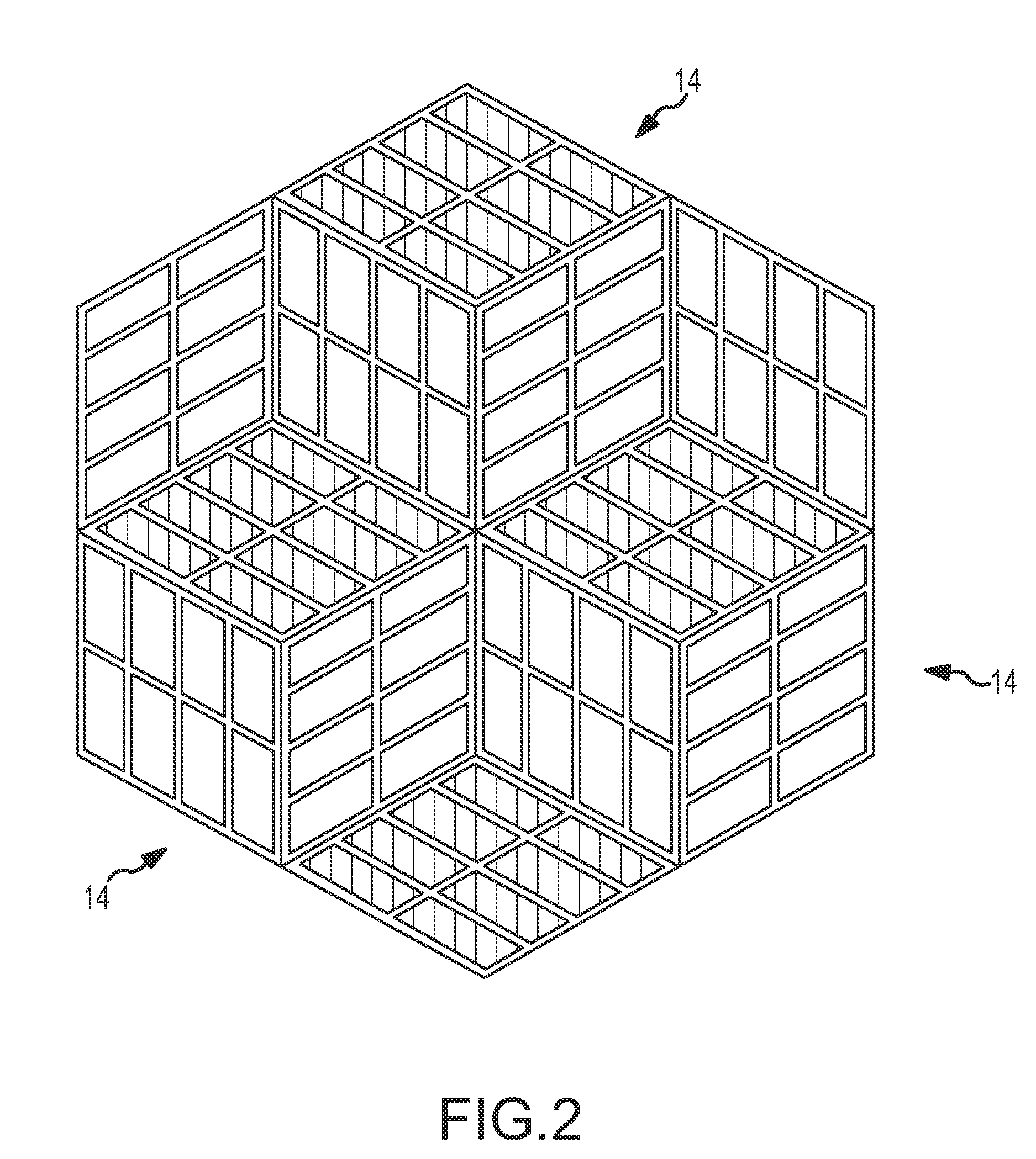
[0015]The illustrated embodiments of the Present Invention are directed to an apparatus for receiving radiant energy from a radiant energy source, such as the sun or any other radiant energy source, and having the ability to convert the received energy into electricity.

[0016]The technology of photo voltaics is an electricity-generating technology in which energy is absorbed and converted into electrical power. In its most common form, photo voltaics provides a method for generating electrical power by using photo voltaic modules, or energy receiving cells, often electrically coupled in plurality, as photo voltaic arrays, and configured to receive and convert energy from the sun (or any other radiant energy source) into electricity. A plurality of energy receiving cells structurally coupled together forms an energy receiving panel. Further, the photo voltaic device within each energy receiving cell receives, or absorbs, the energy, generally through the transduction of radiant energy...


PUM


Abstract

An apparatus for receiving energy is disclosed. The apparatus comprises a support base and a plurality of cells. The support base comprises an electric terminal. The plurality of cells are mounted to the support base. Further, each of the plurality of cells is electrically connected to the electric terminal disposed on the support base. Finally, each of the plurality of cells is oriented in a non-parallel relationship with each neighboring cell.

Description

CROSS REFERENCE To RELATED APPLICATION[0001]The Present Invention claims priority to previously-filed U.S. Provisional Patent Application No. 60 / 971,949, filed on 12 Sep. 2007FIELD OF THE PRESENT INVENTION[0002]The Present Invention relates to the efficient development of solar energy, and more particularly, to an apparatus for increasing the efficiency of photo voltaic cells in a solar energy reception panel.BACKGROUND OF THE PRESENT INVENTION[0003]Photo voltaic systems, which are developed and utilized for generating electric power through the conversion of radiant energy—preferably solar energy, although other sources of radiant or other energy may be applicable—into electricity, are currently known. In such systems, the entire structure of which is sometimes known as an energy receiving panel, a substantially flat portion, or support base, is placed on top of a stationary structure, such as the roof of a building. Alternatively, the support base may be placed on a movable struct...

Claims


Application Information

Patent Timeline
Patent Type & Authority Applications(United States)
IPC IPC(8): H01L31/042
CPCF24J2/54H01L31/042H01L31/0547H02S20/30Y02E10/52F24S30/40
Inventor DAME, CASEY
Owner DAME CASEY
Why Eureka
Try Eureka