Method and apparatus for polarization display of antenna

a technology of polarization display and antenna, applied in the field of antenna techniques, can solve the problems of inability to provide complete polarization information, inconvenient to represent the results on the print media lucidly and in one figur

Inactive Publication Date: 2009-03-19
NXP BV
View PDF0 Cites 7 Cited by
  • Summary
  • Abstract
  • Description
  • Claims
  • Application Information

AI Technical Summary

Benefits of technology

[0011]An object of the present invention is to provide a method and apparatus for polarization display of antenna, which allows to provide complete polarization information for the antenna in each radiation direction.

Problems solved by technology

While the above methods extended and improved the representation capability of the Poincaré sphere and enabled it to be incorporated into experimental and measurement methods, they are not capable of providing complete polarization information and some of these display methods make it inconvenient to represent the results on the print media lucidly and in one FIGURE.

Method used


Image

  • Method and apparatus for polarization display of antenna
  • Method and apparatus for polarization display of antenna
  • Method and apparatus for polarization display of antenna

Examples


Embodiment Construction

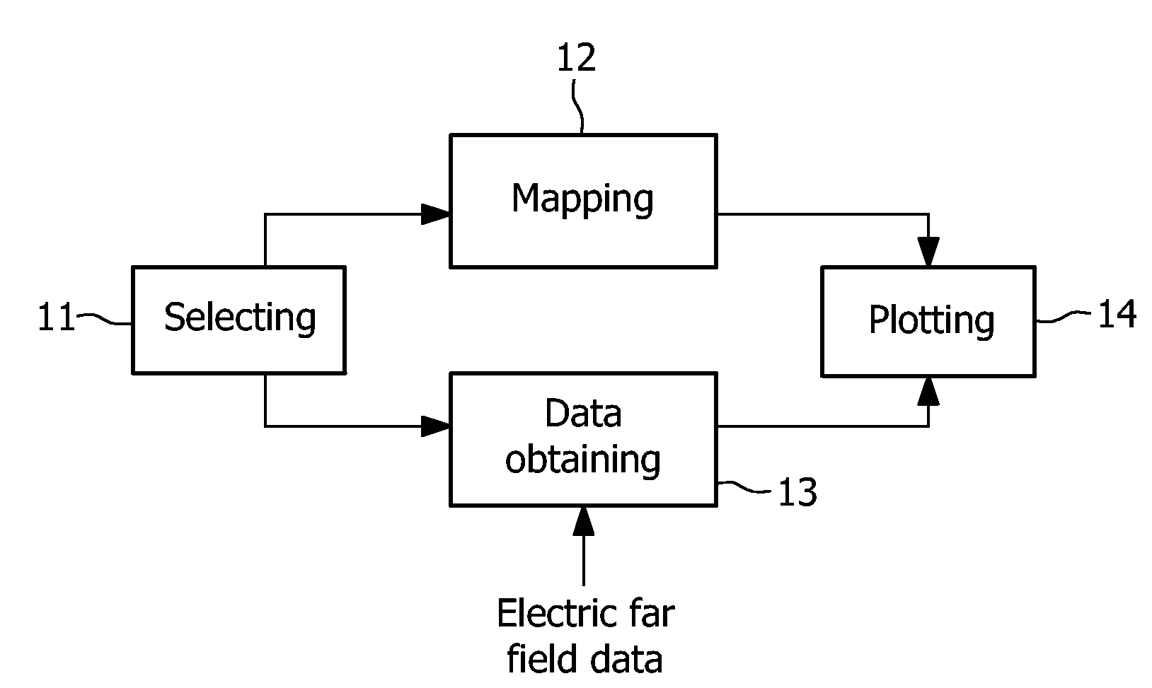
[0041]According to the method for polarization display of antenna as proposed by the invention, a plurality of radiation directions are selected as sample directions from the antenna's radiation directions, and the electric far field data is obtained for each sample direction. Then the selected sample directions are mapped into a plurality of corresponding map points on a two-dimension planar rectangular chart or a spherical chart. Afterwards, according to the electric far field data in each sample direction, the polarization pattern of the radiated far field in each sample direction can be plotted, centered at the corresponding map points in the two-dimension planar rectangular chart or the spherical chart. The method for polarization display of antenna according to the invention may be performed solely through a computer software program, or be incorporated into a conventional antenna simulation testing software.

[0042]A detailed description will be given to the method for polariza...


PUM


Abstract

The invention discloses a method and apparatus for polarization display of antenna. The apparatus for polarization display of antenna comprises a selecting means for selecting a plurality of predetermined radiation directions from radiation directions of an antenna, a mapping means for mapping the plurality of predetermined radiation directions into a coordinates chart, an obtaining means for obtaining corresponding radiation data for the antenna in the plurality of predetermined radiation directions, and a plotting means for plotting a polarization pattern of the antenna in the plurality of predetermined radiation directions on the coordinates chart, according to the radiation data. With the method and apparatus of the invention, all polarization information of the antenna in each radiation direction can be provided with only one FIGURE.

Description

FIELD OF THE INVENTION[0001]The present invention relates generally to antenna techniques, and more particularly, to a method and apparatus for polarization display of antenna.BACKGROUND OF THE INVENTION[0002]Antenna is a radio device used mainly in communication field, with a function to implement transmission and reception of electromagnetic waves in the air. Any electromagnetic wave transmitted by an antenna comprises an electric vector field and a magnetic vector field, which are always orthogonal to each another and are orthogonal to the radiation direction of the electromagnetic wave in the radiation far field. When the antenna transmits the electromagnetic wave, the directions of the electric field vector and the magnetic field vector vary periodically with time in each radiation direction, which is commonly referred to antenna polarization.[0003]To test whether the radiation characteristics of an antenna satisfies various requirements, it's necessary to research the polariza...

Claims


Application Information

Patent Timeline
Patent Type & Authority Applications(United States)
IPC IPC(8): G01R29/10
CPCG01R29/10
Inventor LIU, YONGCONTRACTOR, KAIRAZ S.YUAN, YUN
Owner NXP BV
Why Eureka
Try Eureka