Imaging apparatus and imaging method

a technology of imaging apparatus and image data, applied in the field of imaging apparatus and imaging method, can solve the problems of reducing affecting the application, and affecting the quality of reproduced moving images, so as to reduce the amount of image data captured and increase the compression rate

Inactive Publication Date: 2009-03-19
SONY CORP
View PDF17 Cites 5 Cited by
  • Summary
  • Abstract
  • Description
  • Claims
  • Application Information

AI Technical Summary

Benefits of technology

[0014]Preferably, the transmitting means further transmits data other than the captured image data; and the adjusting means reduces the amount of the image data captured by the imaging means when the transmitting means transmits the other data.
[0017]Preferably, the transmitting step of the first imaging method further includes transmitting data other than the captured image data; and the adjusting step reduces the amount of the image data captured in the capturing step when the transmitting step transmits the other data.
[0020]Preferably, the transmitting means of the second imaging apparatus further transmits data other than the compressed image data; and the adjusting means raises the compression rate when the transmitting means transmits the other data.
[0023]Preferably, the transmitting step of the second imaging method may further include transmitting data other than the compressed image data, and the adjusting step raises the compression rate when the transmitting step transmits the other data.
[0026]Preferably, the transmitting means of the third imaging apparatus further transmits data other than the compressed image data, and the adjusting means reduces the amount of the image data captured by the imaging means while raising the compression rate when the transmitting means transmits the other data.
[0029]Preferably, the transmitting step of the third imaging method further includes transmitting data other than the compressed image data; and the adjusting step reduces the amount of the image data captured in the capturing step while raising the compression rate when the transmitting step transmits the other data.

Problems solved by technology

Where a data-receiving destination apparatus has a low processing capability or where network congestion between the sending and the receiving apparatuses are lowering transfer rates, the growing data quantity can lead to overflows of communication processes or missing frames in reproduced moving images.
This solution, however, unnecessarily degrades the quality of reproduced moving images in cases where high-speed communication is available.
Another disadvantage is that the second solution is not fit for applications where moving image data about the object are to be supplied in real time.
A further disadvantage is that the compression rate of the prepared second image data may or may not be suitable for the ongoing status of communication.

Method used


Image

  • Imaging apparatus and imaging method
  • Imaging apparatus and imaging method
  • Imaging apparatus and imaging method

Examples


Embodiment Construction

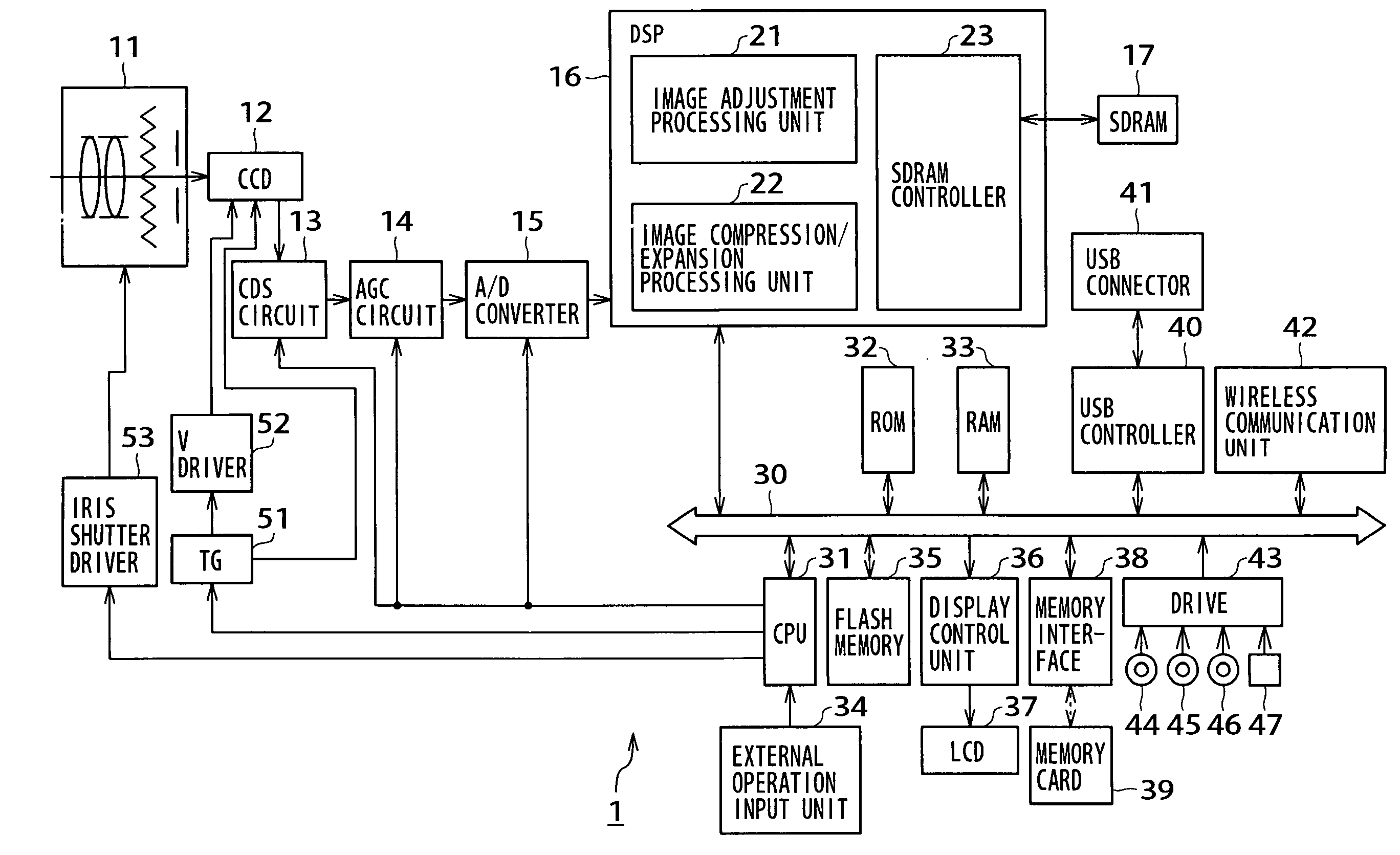
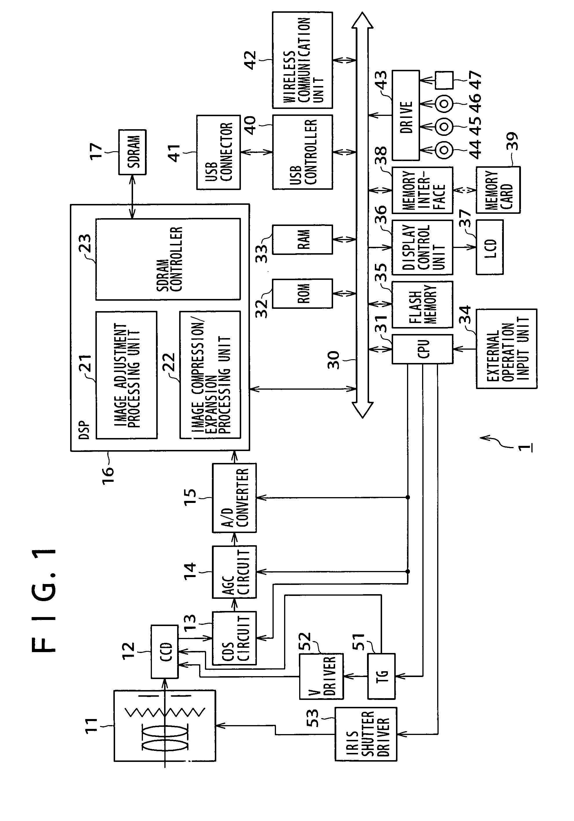
[0059]FIG. 1 is a block diagram showing the basic structure of a mobile phone equipped with a camera function according to the invention.

[0060]Light from an object, not shown, enters a CCD (charge-coupled device) 12 through a lens unit 11 of the mobile phone 1 that includes lenses and an iris mechanism. The entered light is subjected to a photoelectric conversion process.

[0061]A video signal output by the CCD 12 is supplied to a CDS (correlated double sampling) circuit 13. This circuit removes noise components from the input signal by submitting the signal to a correlated double sampling process. The signal thus processed is output to an AGC (automatic gain control) circuit 14. The AGC circuit 14 controls the gain of the input signal before outputting the controlled signal to an A / D (analog / digital) converter 15. The A / D converter 15 converts the input analog signal to a digital signal that is output to a DSP (digital signal processor) 16.

[0062]The DSP 16 generates control signals s...


PUM


Abstract

An imaging apparatus and an imaging method supply an optimum amount of image data to another apparatus. When a PDA has a maximum transfer rate of 1.5 Mbps, a mobile phone determines that the maximum speed of communication with the PDA is low, reduces the amount of moving image data captured by a CCD of the mobile phone accordingly, and supplies the captured moving image data to the PDA. The PDA therefore displays a low-quality moving image on its display unit. When the PDA has a maximum transfer rate of 480 Mbps, the CPU of the mobile phone leaves unchanged the amount of moving picture data captured by the CCD and supplies the captured moving image data to the PDA. The PDA then displays a high-quality moving image on its display unit. The foregoing may be advantageously applied to digital cameras.

Description

CROSS-REFERENCE TO RELATED APPLICATIONS[0001]This application is a continuation of U.S. application Ser. No. 10 / 496,890, filed Feb. 23, 2005, the disclosure of which is incorporated herein by reference.BACKGROUND OF THE INVENTION[0002]The present invention relates to an imaging apparatus and an imaging method. More specifically, the invention relates to an imaging apparatus and an imaging method for supplying an optimum amount of image data to another apparatus.[0003]The popularization in recent years of imaging apparatus, such as digital video cameras, has entailed significant improvements in the resolution of camera equipment, such as the incorporation of a CCD (charge-coupled device) in each apparatus. There also is a recent trend toward a growing number of feature-rich models of imaging apparatus represented by digital video cameras furnished with a communication function and mobile phones with an imaging function.[0004]Typically, a digital video camera equipped with a USB (Univ...

Claims


Application Information

Patent Timeline
Patent Type & Authority Applications(United States)
IPC IPC(8): H04N5/225G06K9/36H04N1/00H04N5/232H04N5/335H04N5/372
CPCH04N1/00307H04N1/00347H04N5/232H04N2201/0025H04N2201/0027H04N5/23222H04N2201/0049H04N2201/0065H04N2201/0096H04N19/46H04N19/164H04N2201/0041H04N23/661H04N23/951H04N23/63H04N23/64
Inventor YOSHIDA, CHISATODATE, OSAMU
Owner SONY CORP
Why Eureka
Try Eureka