Eureka AIR delivers breakthrough ideas for toughest innovation challenges, trusted by R&D personnel around the world.

Printing press equipped with color chart measuring apparatus

a color chart and measuring apparatus technology, applied in the field of printing presses, can solve the problems of large image data processing time, unsuitable print jobs, and inability to prepare reference images, so as to achieve the effect of reducing the amount of image data to be handled

Inactive Publication Date: 2005-03-01
DAINIPPON SCREEN MTG CO LTD
View PDF42 Cites 4 Cited by
  • Summary
  • Abstract
  • Description
  • Claims
  • Application Information

AI Technical Summary

Benefits of technology

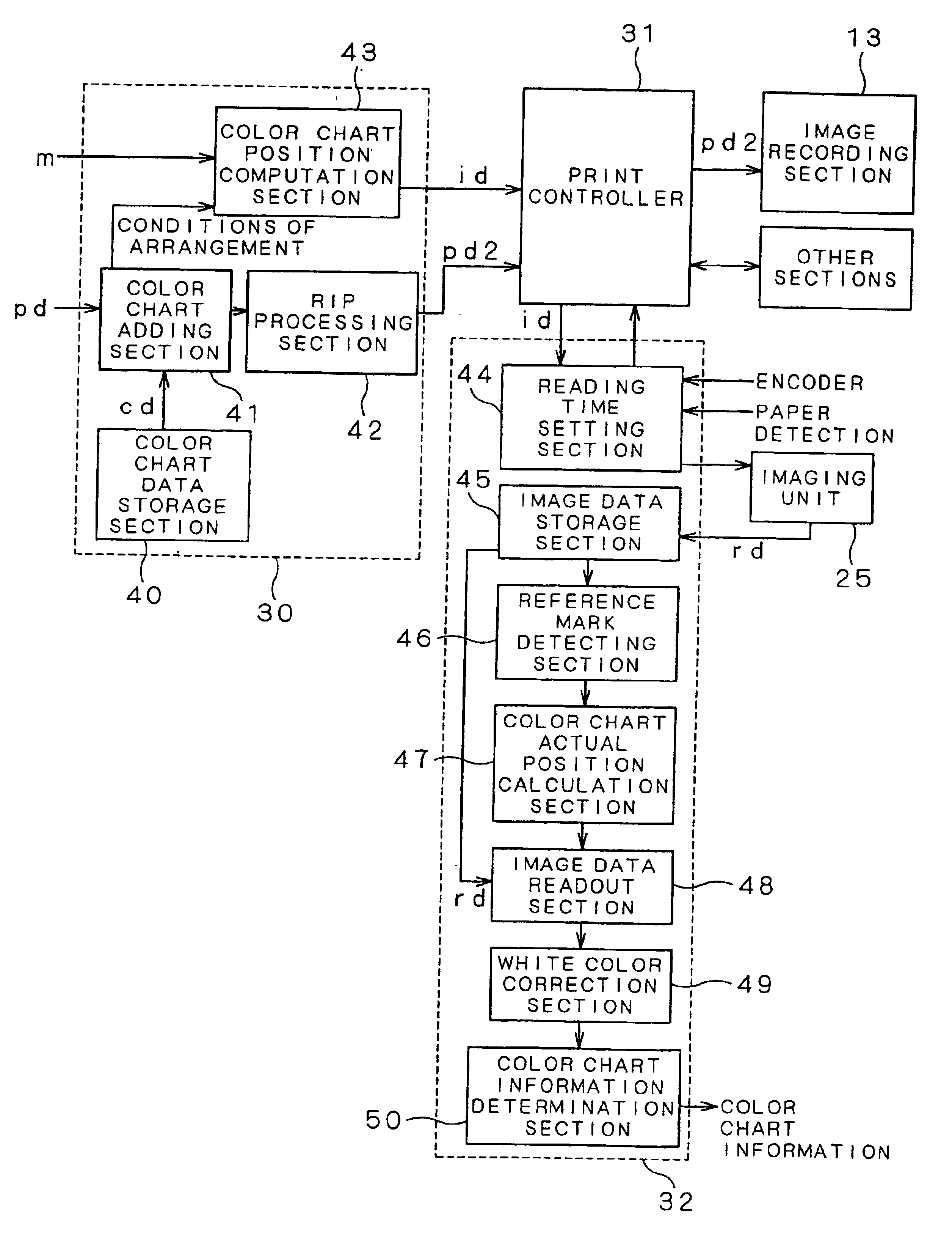
The present invention is intended to solve the aforementioned conventional problems, and an object thereof is to provide a printing press equipped with a color chart measuring apparatus for providing a color chart on printing matter, instead of reading a whole image of the printing matter, and then reading and measuring only an area relating to the color chart on printing paper being transported. In this case, the amount of image data to be handled can be reduced and the use of the color chart avoids the necessity of preparing a reference image.
In the twenty-fourth, a tilt of the color chart imaged can be corrected by using at least two reference marks. This is especially effective for a tilt of printing paper due to transportation, when color chart measurement is made while printing matter is being transported.

Problems solved by technology

The above conventional technique, however, has a problem that reading and comparing a whole image of printing matter with a reference image requires handling of a large amount of image data and requires much time for image data processing.
In addition, the preparation of a reference image is not suitable for print jobs which require immediacy, such as multi-kinds, small-circulation printing.

Method used


Image

  • Printing press equipped with color chart measuring apparatus
  • Printing press equipped with color chart measuring apparatus
  • Printing press equipped with color chart measuring apparatus

Examples


Embodiment Construction

[Preferred Embodiments of Color Chart]

First of all, the structure of a color chart used in the present invention will be set forth. FIGS. 6A to 6D are explanatory diagrams showing a concrete example of a color chart according to the present invention. Referring to FIG. 6A, an image (im) representing printing matter and a color chart (cc) are printed on printing paper S, the color chart (cc) being located along the rear end of the image (im) with respect to a print direction. The image (im) on the printing paper S is positioned a predetermined gripper margin (f) apart from the leading edge (gripper end) of the printing paper S. Where (m) is the size of the image (im) (in the print direction), (r) is the width of the color chart (cc), and the leading edge of the printing paper S is an origin point, the area where the color chart (cc) is to be located is in the range from a point at a distance of ((f)+(m)) from the original point to a point at a distance of ((f)+(m)+(r)) from the origi...


PUM


Abstract

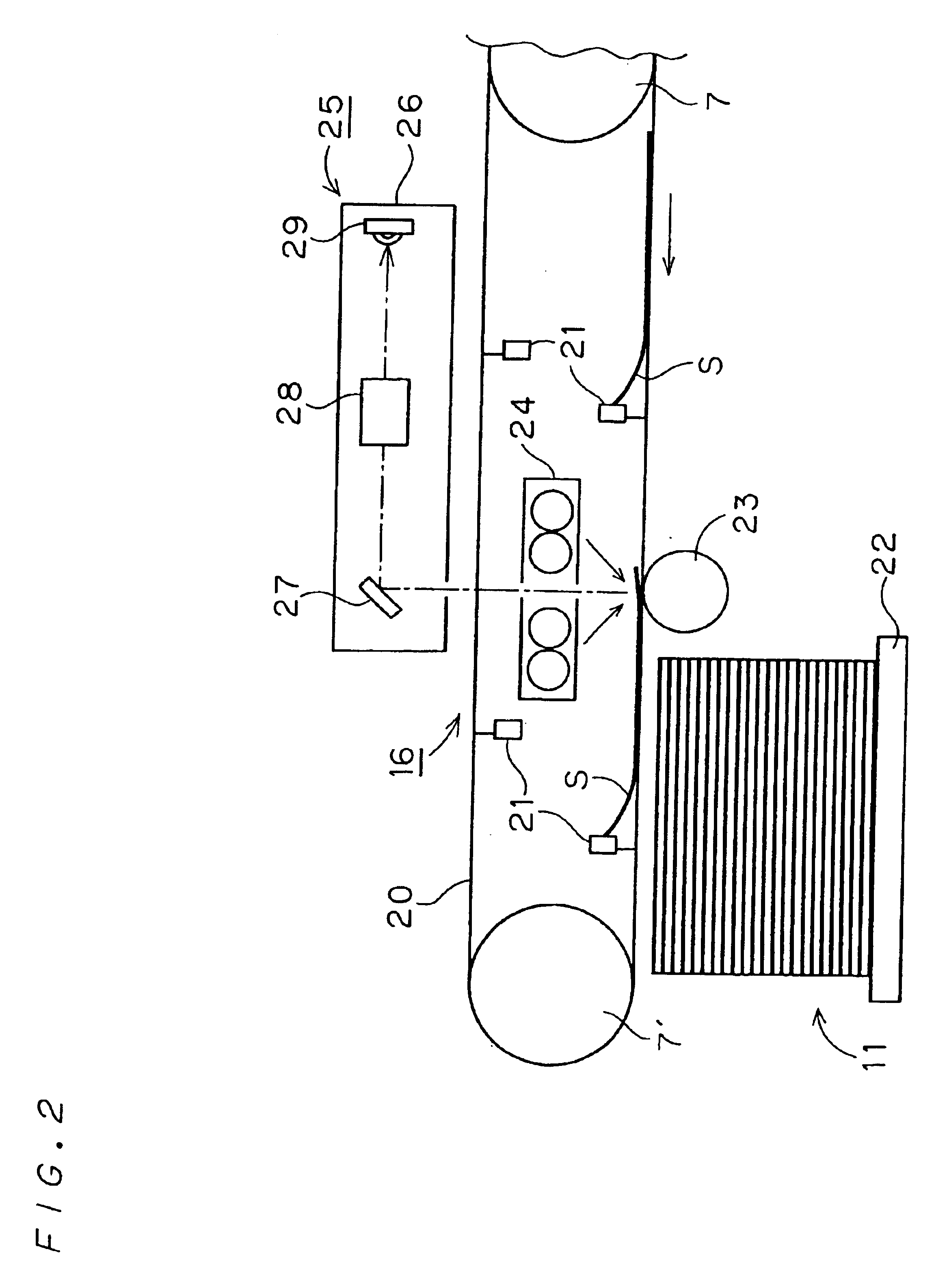
A reading time setting section (44) determines a read area for an imaging section (25) on the basis of color chart positional data (id). The imaging section (25) reads an image on printing paper during the reading time and readout image data (rd) is stored in an image data storage section (45). A reference mark detecting section (46) detects the positions of reference marks from the readout image data (rd). A color chart actual position calculation section (47) corrects a tilt of a color chart determined from the positions of the reference marks and calculates an actual position of each of color chart fields (cr). An image data readout section (48) reads out image data on a color chart field corresponding to the calculated actual position. At the same time, image data on a white color field immediately above the color chart field is also read out. A white color correction section (49) produces a white reference on the basis of the image data on the white color field and corrects the image data on the color chart field. A color chart information determination section (50) measures color chart information, such as a color density and a dot percentage, about each of the color chart fields. This printing press determines a reading time on the basis of the position of the color chart at the time of printing plate recording and thereby allows imaging of an area including the color chart on the printing paper being transported.

Description

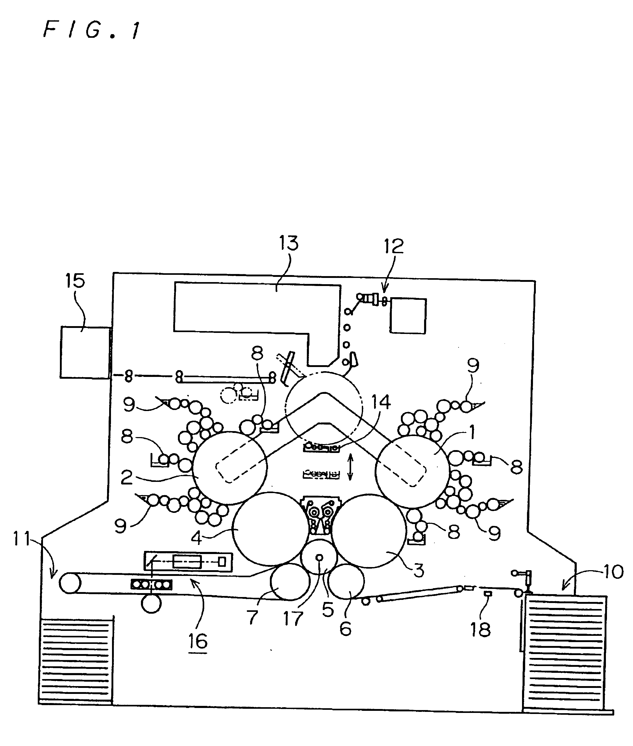
BACKGROUND OF THE INVENTION1. Field of the InventionThe present invention relates to a printing press for doing printing such as offset printing in which inks are applied to printing plates to form ink images, which are then transferred onto printing paper. And especially, the present invention relates to a printing press equipped with a color chart measuring apparatus for reading a color chart printed on printing paper to acquire color chart information.2. Description of the Background ArtRecently, printing presses which install therein a plate making machine (printing plate recording apparatus) for forming an image on a printing plate on the basis of digital image data, known as a CTP (computer-to-plate) machine, have been developed for commercial use. Such printing presses are called digital printing presses and are suitable for short-time print jobs such as multi-kinds, small-circulation printing, since they can produce printed matter directly from image data. Those digital prin...

Claims


Application Information

Patent Timeline
Patent Type & Authority Patents(United States)
IPC IPC(8): B41F33/00
CPCB41F33/0036H04N1/00015H04N1/00023H04N1/00031H04N1/00045H04N1/0005H04N1/00063H04N1/00087H04N1/00718H04N1/00737H04N1/00761H04N1/00774B41F33/0081H04N2201/04767B41P2227/70B41P2233/51H04N2201/04703H04N2201/04718H04N2201/04732
Inventor OKUDA, TSUYOSHI
Owner DAINIPPON SCREEN MTG CO LTD
Why Eureka
Eureka Blog
Learn More