Cost efficient spectral-reuse transceiver

Inactive Publication Date: 2009-03-19
BONE VALLEY PATENTS
View PDF8 Cites 63 Cited by
  • Summary
  • Abstract
  • Description
  • Claims
  • Application Information

AI Technical Summary

Benefits of technology

[0012]A first of these parameter sets lowers the microprocessing and memory required of the transceiver, so that lower-cost components can be used. A second of these parameter sets further lowers the microprocessing and memory required of the transceiver and improves the clear sub-channel assessment.
[0013]In another embo

Problems solved by technology

Because secondary users must not interfere with primary users, complaints of interference from a primary user to the FCC may result in its issuing an administrative order requiring that the secondary user move to another portion of the band

Method used


Image

  • Cost efficient spectral-reuse transceiver
  • Cost efficient spectral-reuse transceiver
  • Cost efficient spectral-reuse transceiver

Examples


Embodiment Construction

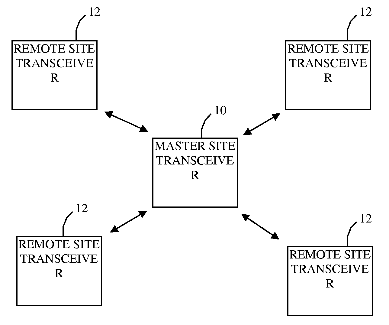
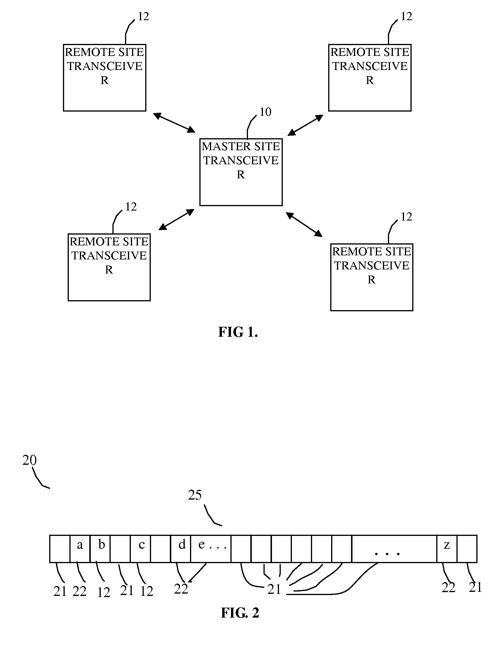
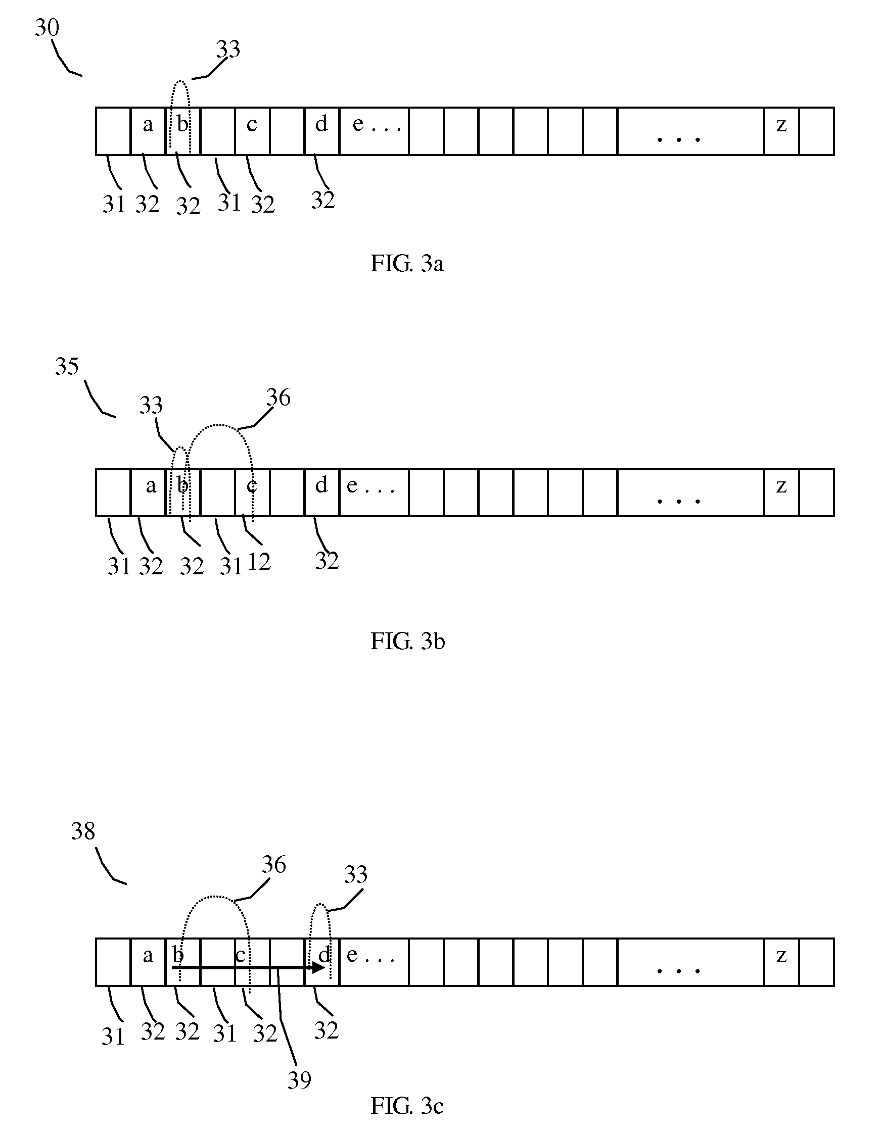
[0023]Before describing the details of the ‘cost efficient’ spectrum reuse transceiver of the present invention, it should be observed that the invention essentially involves special cases of the sub-channel hopping control mechanism executed by the communications control processor of the spectral reuse transceiver of the type disclosed in the above-referenced '753 application, that involves the execution of one or more prescribed discriminators or sub-channel selection filters, so as to effectively reduce the receiving end of a transceiver link. As will be described, these filter functions are readily implemented by appropriately setting the configuration parameters used by the communications controller of the transceiver disclosed in the '753 application to control the operation of the transceiver. The architecture of the transceiver of the '753 application remains unchanged, except as noted. As a consequence, the present invention has been illustrated in the drawings by readily u...


PUM


Abstract

An operational mechanism enables frequency re-use techniques, including selective frequency hopping and channel aggregation, on very low-cost transceiver hardware.

Description

CROSS-REFERENCE TO RELATED APPLICATIONS[0001]The present application is a continuation-in-part of and claims the benefit of previously filed, co-pending U.S. patent application, Ser. No. 10 / 730,753, filed Dec. 8, 2003, by Brent Saunders et al, entitled: “Radio Communication System Employing Spectral Reuse Transceivers” (hereinafter referred to as the '753 application), and further claims the benefit of previously filed, co-pending U.S. patent application Ser. No.: 11 / 532,306, filed Sep. 15, 2006 by E. Gerhardt et al., entitled: “Spectral Reuse Transceiver-based Aggregation of Disjoint, Relatively Narrow Bandwith (voice) Channel Segments of Radio Spectrum for Wideband RF Communication Applications” (herein referred to as the '306 application), which incorporates by reference and claims priority to U.S. Patent Application Ser. No. 60 / 784,105, filed Mar. 20, 2006, by E. Gerhardt et al, entitled: “Link Utilization Mechanism for Aggregation of Disjoint Radio Bandwidth,” (herein referred ...

Claims


Application Information

Patent Timeline
IPC IPC(8): H04B1/00
CPCH04B1/7143H04B1/715H04B7/2621H04B2001/7154H04L5/0005H04L5/0037H04W88/08H04W24/00H04W24/10H04W72/02H04W72/042H04W72/0426H04W74/08H04W16/14H04W72/27H04W72/23
Inventor KATTWINKEL, BRYAN
Owner BONE VALLEY PATENTS
Why Eureka
Try Eureka