Method and System for Determining a Force and/or Torque Applied to an Orthodontic Bracket

Inactive Publication Date: 2009-03-19
SEARS ROBERT STEVEN +1
View PDF7 Cites 13 Cited by
  • Summary
  • Abstract
  • Description
  • Claims
  • Application Information

AI Technical Summary

Benefits of technology

[0005]In especially preferred embodiments, the present invention includes a force-responsive orthodontic bracket having a lower base member, an upper bracket member, and an elastomeric layer interposed betwe

Problems solved by technology

Adjustment of the archwire is, how

Method used


Image

  • Method and System for Determining a Force and/or Torque Applied to an Orthodontic Bracket
  • Method and System for Determining a Force and/or Torque Applied to an Orthodontic Bracket
  • Method and System for Determining a Force and/or Torque Applied to an Orthodontic Bracket

Examples


Embodiment Construction

System Components

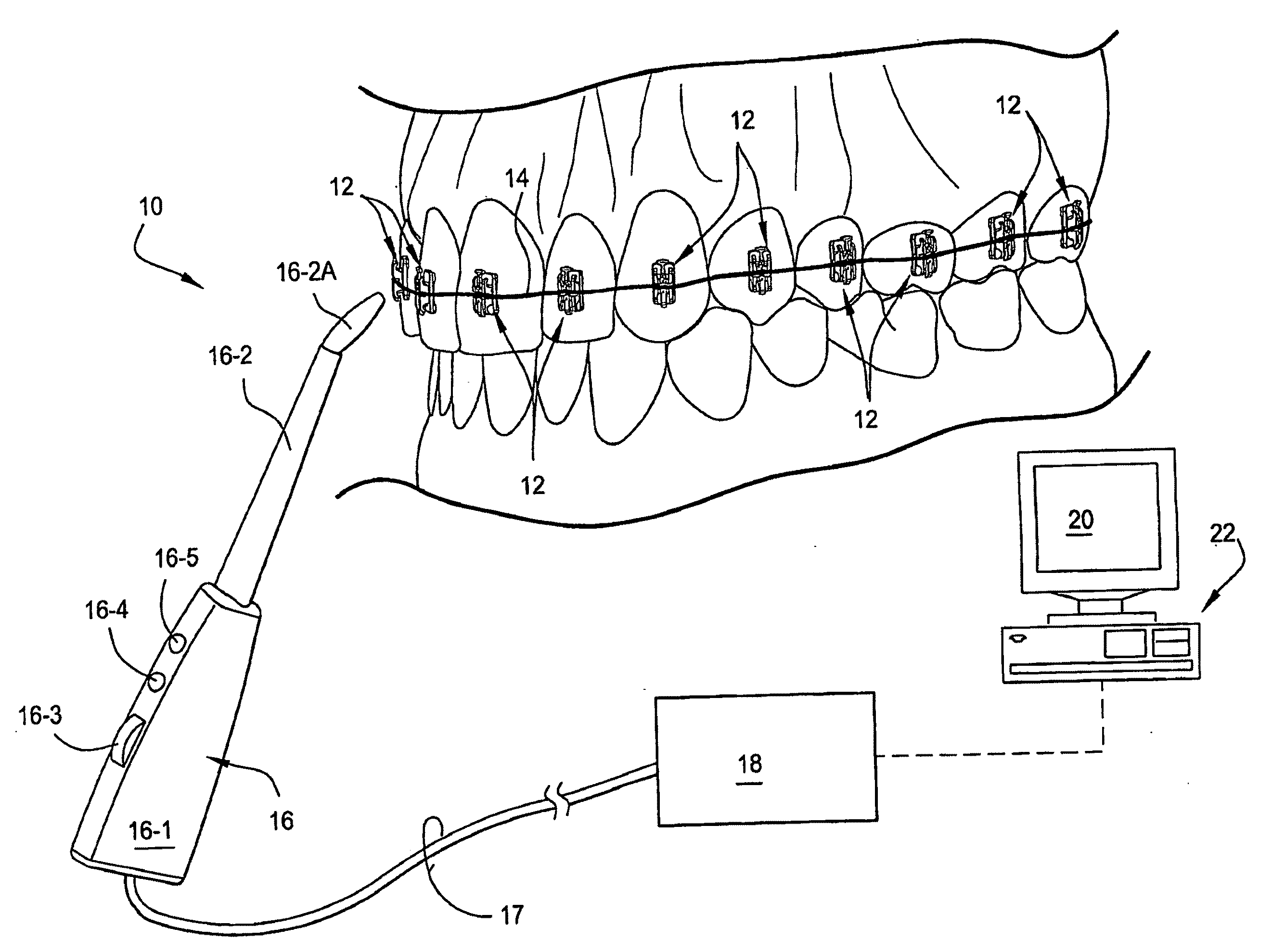
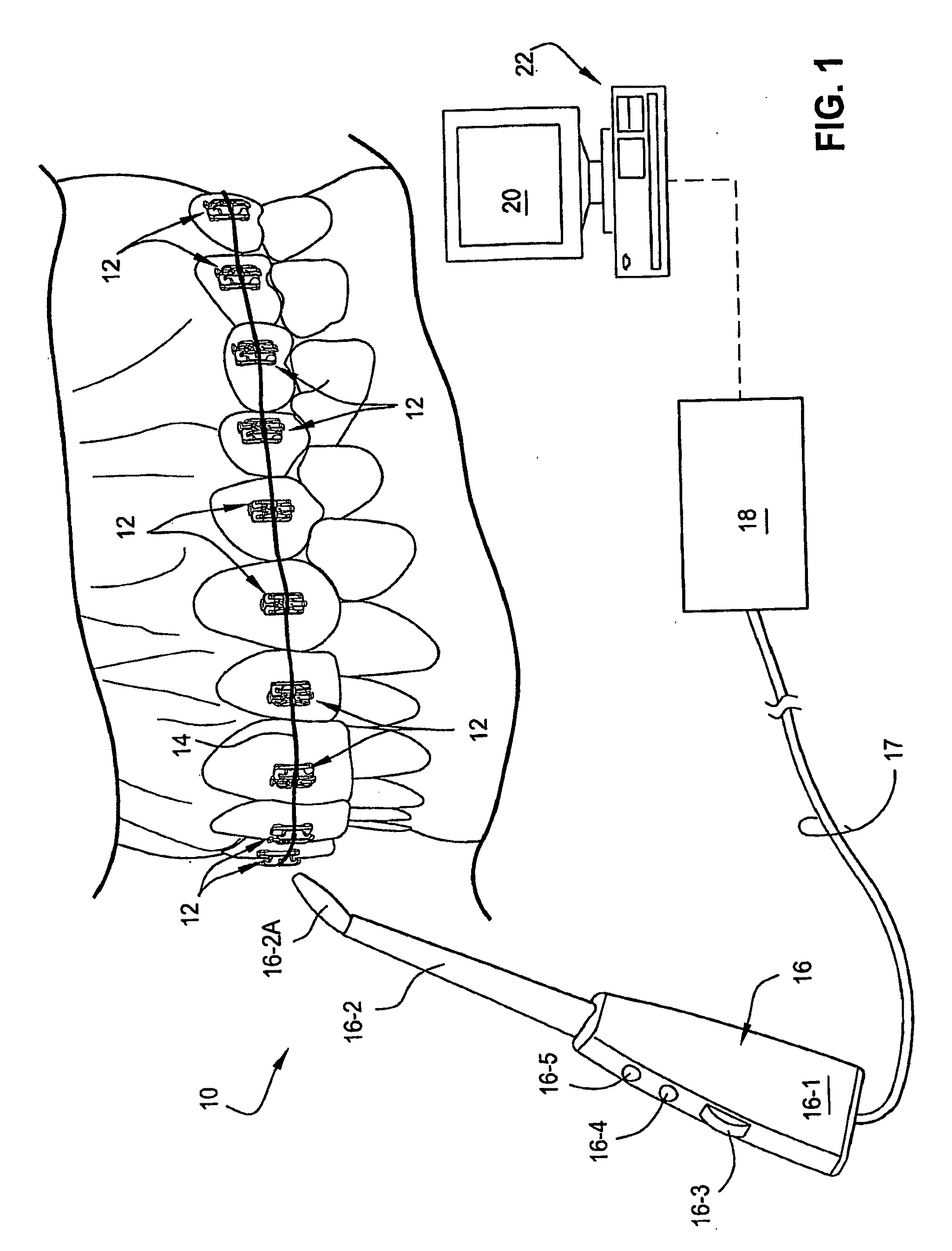
[0031]FIG. 1 depicts schematically a system 10 according to the present invention which is especially adapted to detect and present the magnitude and / or direction of force associate with individual ones of the orthodontic brackets 12 which are bonded to the front surfaces of respective teeth in a patient's mouth. As will be explained in greater detail below, the individual brackets 12 are provided with fiducial marks that are indicative of the magnitude and / or direction of force applied to the brackets 12 by means of an archwire 14 attached to, and extending along, the brackets 12.

[0032]Generally, according to the present invention, the fiducial marks may be detected optically by means of a hand-held optical detector 16 which takes digital pictures of the fiducial marks and which is operatively connected to a central processor 18 by a signal line 17. The central processor 18 thus receives output signals generated by means of the optical detector 16 via the signal li...


PUM


Abstract

A method and system are disclosed for analyzing images of fiducials that provide an indication of the forces and/or torques applied to an orthodontic bracket. The mass of each of the pixels forming the fiducial image are multiplied by the square of the distance of the pixel along the image's x axis, the product of the distances of the pixel along the image's x and y axes, and the square of the distance of the pixel along the image's y axis. The second order moments of inertia about the centroid of the fiducial are calculated and used to form a first matrix. The first matrix is diagonalized into a second matrix, from which the fiducial 's first and second principal axes are determined. These axes are then used to measure the size of the fiducial in the image.

Description

CROSS-REFERENCE TO RELATED APPLICATION[0001]This application claims the benefit of Provisional Application No. 60 / 796,524, filed May 2, 2006, the entire contents of which is hereby incorporated by reference in this application.BACKGROUND OF THE INVENTION[0002]The present invention relates generally to the field of orthodontics. In especially preferred embodiments, the present invention relates to orthodontic brackets which include a force-responsive component by which the magnitude and / or direction of an applied force may be determined optically.BRIEF DESCRIPTION OF THE INVENTION[0003]Orthodontic brackets typically are attached to individual teeth and connected to an archwire so as to apply appropriate force over time to move and straighten teeth. Specifically, teeth are moved and rotated by applying forces to the brackets via the archwire. Periodic visits to the orthodontist are therefore required so that the assembly may be checked and adjusted to ensure the proper amount and dire...

Claims


Application Information

Patent Timeline
IPC IPC(8): G06K9/00
CPCG06T2207/30204G06T7/2033G06T7/246
Inventor SEARS, ROBERT STEVENTRIMMER, WILLIAM STUART
Owner SEARS ROBERT STEVEN
Why Eureka
Try Eureka