Ball joint device

a technology of ball joint and ball joint, which is applied in the direction of mechanical equipment, basic electric elements, couplings, etc., can solve the problems of shortening the useful life, series of inadmissible flaws, and inability to assembly, so as to reduce the cost of the device, ensure leakage tightness, and simplify the manufacturing process

Inactive Publication Date: 2009-03-19
IND AUXILIAR ALAVESA S A INAUXA
View PDF25 Cites 9 Cited by
  • Summary
  • Abstract
  • Description
  • Claims
  • Application Information

AI Technical Summary

Benefits of technology

[0010]The design of the joining means and the contact areas of the components of the ball joint device on the joint surfaces assures the leak-tightness required in this type of devices. Said joining means also allow simplifying the process of manufacturing the device, given that leaks in the contact areas are absorbed by the configuration itself of said means; the notching or grooving included in the contact areas between the casing and the ball joint seat.
[0011]The relationship between the casing and the seat can also allow the casing to be designed such that it can be adapted to different applications according to the system in which the ball joint device is going to be incorporated.
[0012]On the other hand, the casing and the seat define a housing in which the protective dome is joined at one of its ends to the ball joint device; the use of a retaining element for said protective dome is thus prevented, achieving a reduction of the cost of the device, both by decreasing the number of components and by simplifying the assembly.
[0042]On the other hand, the protective dome can comprise a plurality for annular grooves in the manner of a labyrinthine seal in a contact surface between the first end and the ball joint to assure leak-tightness between the protective dome and the ball joint.

Problems solved by technology

This high degree of precision in the manufacture is necessary because it could even occur that the assembly is not possible if the tolerances of the components are too broad or if, even in the case of being more restrictive, the manufactured parts do not comply with said design tolerances; these tolerances will also have an effect on the functioning of the device.
Ball joint devices with inappropriate tolerances cause a series of inadmissible flaws.
In addition to being noticeable in a recently manufactured device, these flaws imply a premature deterioration of the device, shorten its useful life and affect the use of the device.
Another feature which ball joint devices must have is leak-tightness.
The devices known in the state of the art have a design and construction which does not facilitate this ability to be integrated in a system in a manner easily adaptable to different systems, given that to that end, they require that the system itself is modified.

Method used


Image

  • Ball joint device
  • Ball joint device
  • Ball joint device

Examples


Embodiment Construction

[0095]A preferred embodiment of the invention is described below with the aid of the figures.

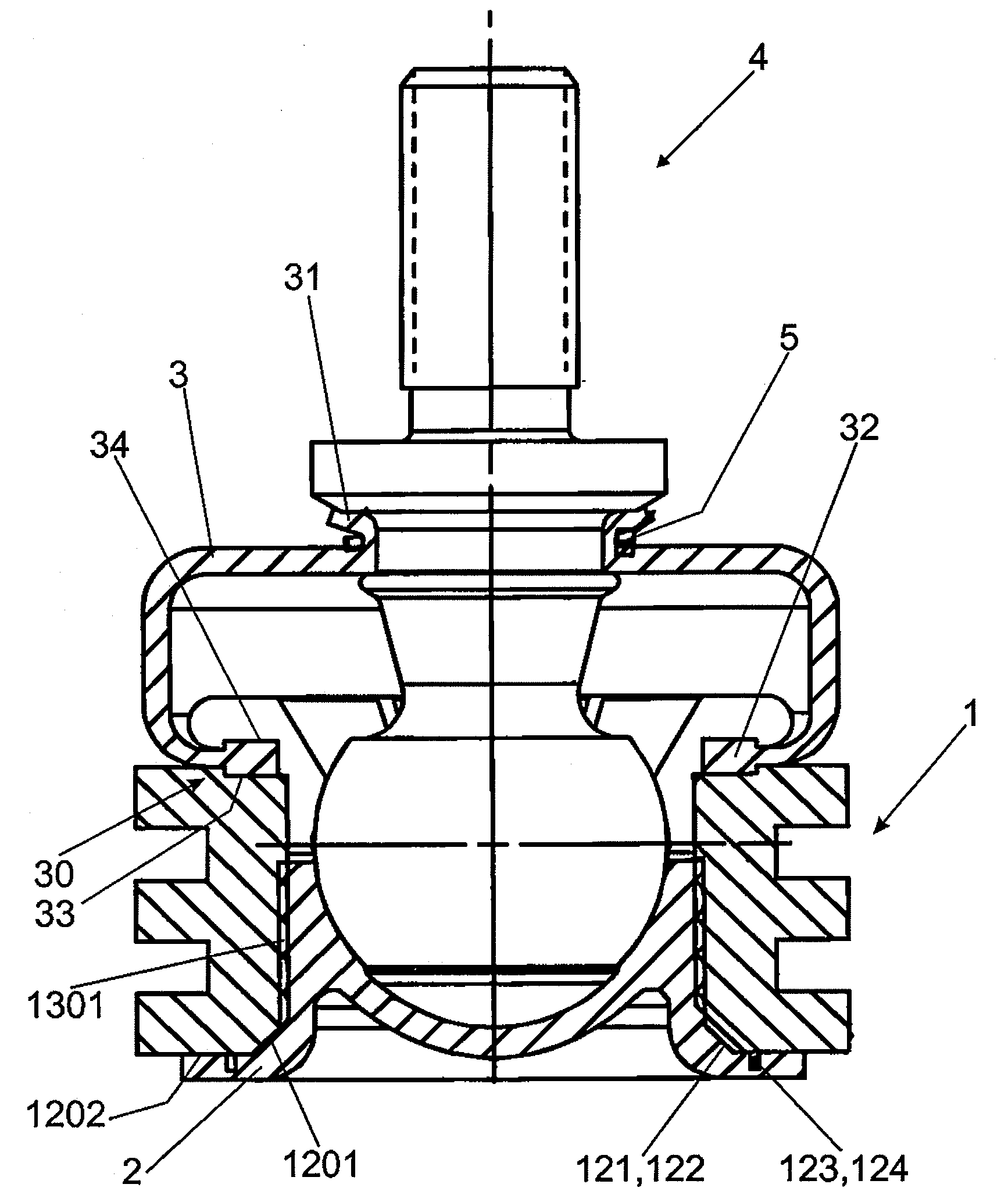
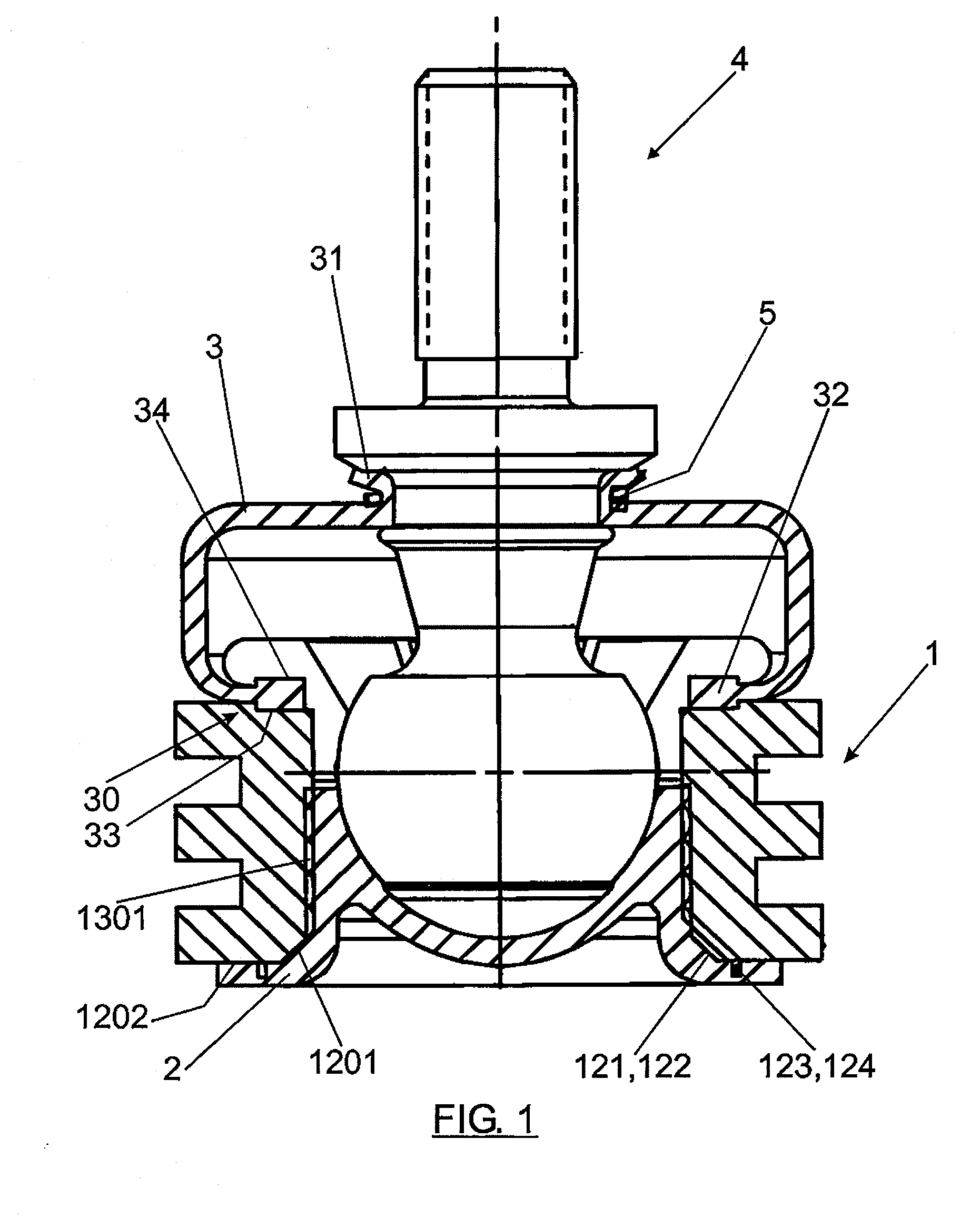
[0096]FIG. 1 depicts an embodiment of the device of the invention in which the different components are shown assembled.

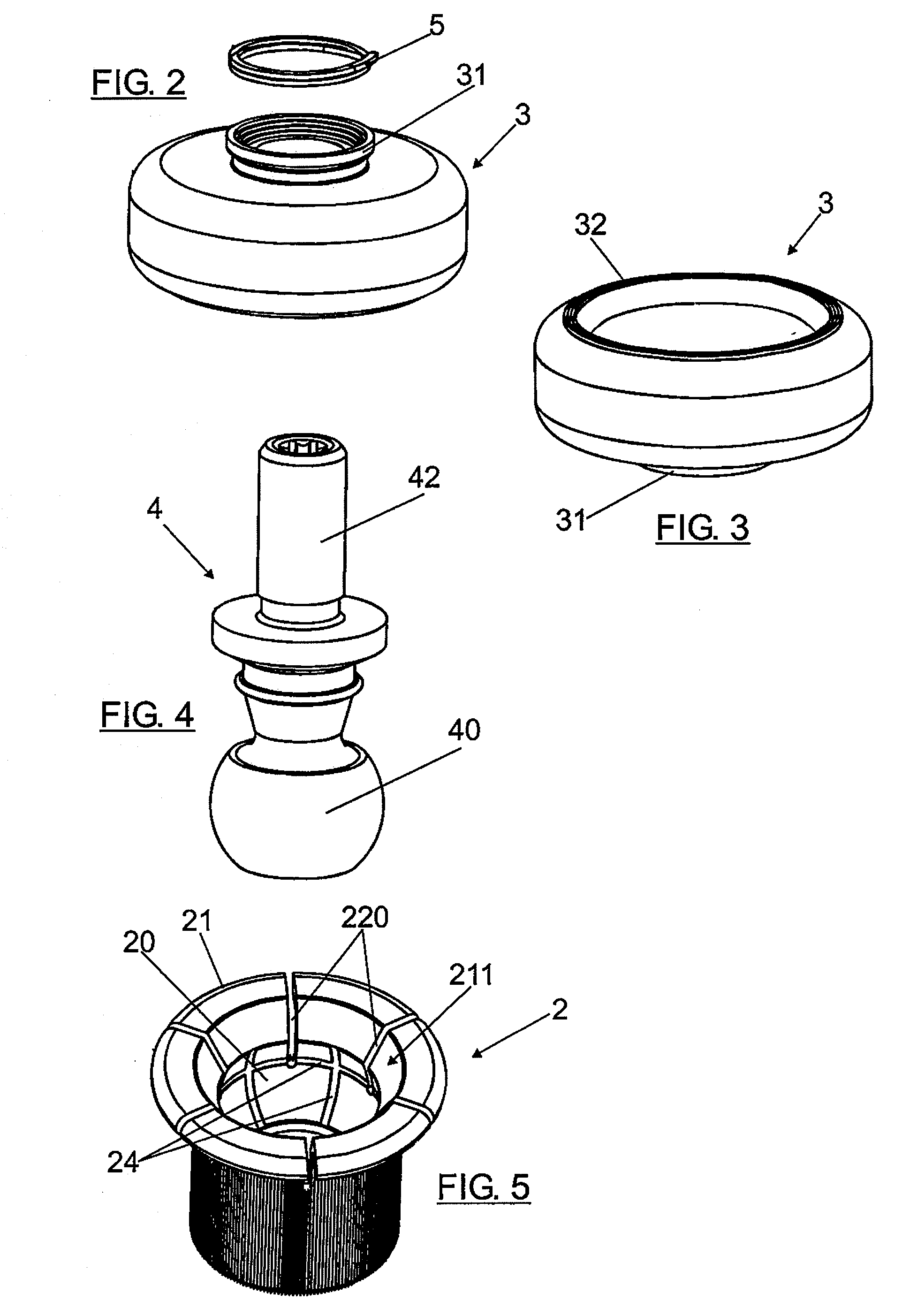
[0097]In FIGS. 5 and 6, the seat 2 is shown in its configuration before being assembled in the device; in FIG. 1, the seat 2 after having been introduced in the housing 10 of the casing 1 can be observed. In this sense, FIGS. 5 and 6 show an area of the seat 2 which once formed, together with the second casing 1 end 12, constitutes the first frontal contact surface 1202 and the first peripheral contact surface 1201.

[0098]The joint between the casing 1 and the ball joint seat 2 is carried out according to the materials of said casing 1 and seat 2. If the joint between the materials is plastic-plastic, the joint will be welding; should one of the materials not be plastic, the joint will be riveting.

[0099]As can be seen in FIG. 1, there are three contact surfaces 1201, 1202 an...


PUM


Abstract

A ball joint device having a ball joint (4), a ball joint seat (2) and a casing (1). The casing (1) has a first casing housing (10) to house the seat (2), said first casing housing (10) being configured to prevent relative movement between the casing (1) and the seat (2). The casing (1) also has a first casing end (11); a second casing end (12) opposite to the first casing end (11) having first joining elements (120) between the casing (1) and the seat (2); an intermediate portion (13) in the first casing housing (10) between the first casing end (11) and the second casing end (12), said intermediate portion (13) having second joining elements (130) between the casing (1) and the seat (2).

Description

[0001]This application is a Continuation of application Ser. No. 11 / 284,057, filed 21 Nov. 2005, and which applications are incorporated herein by reference.FIELD OF THE INVENTION[0002]The invention refers to a ball joint device of the type used in automotive industry.BACKGROUND OF THE INVENTION[0003]Different embodiments disclosing ball joint devices are known in the state of the art.[0004]European patent EP 0481212 shows a ball joint with a ball head, a pivot pin and a ball joint pin housed in a joint casing with a pot-shaped interior, in which it can be moved in a pivoting manner. The ball joint is assembled in a sliding manner in a bearing joined to the joint casing. The device has an annular projection radially extending outward touching the front face of the side of the opening of the joint casing.[0005]However, the embodiments proposed in the state of the art require a precise adjustment both in the manufacture and in the subsequent assembly of the components of the device. T...

Claims


Application Information

Patent Timeline
Patent Type & Authority Applications(United States)
IPC IPC(8): F16C11/00
CPCF16C11/0638F16C11/0671Y10T403/32631Y10T403/32204F16C11/069B60G2204/416B60G2204/42B60G2204/4404F16C11/0685
Inventor MORALES ARNAEZ, AGUSTIN
Owner IND AUXILIAR ALAVESA S A INAUXA
Why Eureka
Try Eureka