90-Degree ferrule and pin terminals

a technology of ferrules and pin terminals, which is applied in the direction of securing/insulating coupling contact members, coupling device connections, and connections effected by permanent deformation, etc., can solve the problems of weakening and eventually breaking, limiting the space required to insert ferrules or pin terminals straight into the terminal block located inside the control panel or enclosure, and achieving the effect of facilitating termination

Inactive Publication Date: 2009-03-19
THOMAS & BETTS INT INC
View PDF14 Cites 4 Cited by
  • Summary
  • Abstract
  • Description
  • Claims
  • Application Information

AI Technical Summary

Benefits of technology

[0009]In accordance with the present invention, a ferrule or pin terminal is provided with a bend to facilitate terminations in confined or restricted spaces and provides consistency and uniformity. The ferrule terminal embodiment of the present invention includes a ferrule portion and a barrel portion. The ferrule portion includes a cylindrical wall, a first end, a second end, a longitudinal axis and an aperture. The aperture is located in the cylindrical wall between the first and second ends. The ferrule portion is bent along the longitudinal axis to form a bend. The bend in the longitudinal axis has an angle of from about 15 to about 120 degrees, preferably from about 60 to about 90 degrees. The aperture in the ferrule portion is a stress relief aperture, which preferably has four sides and four rounded corners. The stress relief aperture can also have a substantially round or oval shape.

Problems solved by technology

As a consequence, the space required to insert ferrules or pin terminals straight into a terminal block located inside a control panels or enclosures is often limited.
The disadvantage of this construction is that, when there is limited space due to close proximity of other components or obstructions, it is difficult to insert the ferrule or pin terminal into the terminal block.
However, bending the terminals in this manner can cause them to weaken and eventually break over time, especially when they may be subjected to vibration or movement.
The end result is a termination that is often inconsistent and highly unreliable.

Method used


Image

  • 90-Degree ferrule and pin terminals
  • 90-Degree ferrule and pin terminals
  • 90-Degree ferrule and pin terminals

Examples


Embodiment Construction

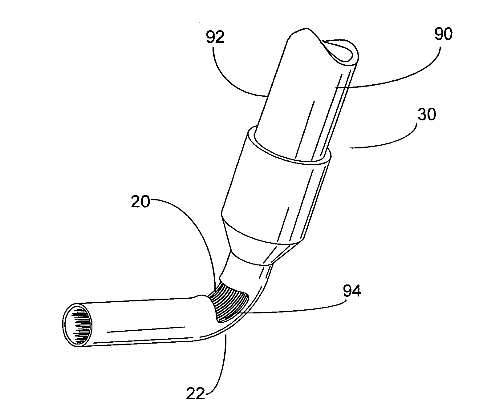
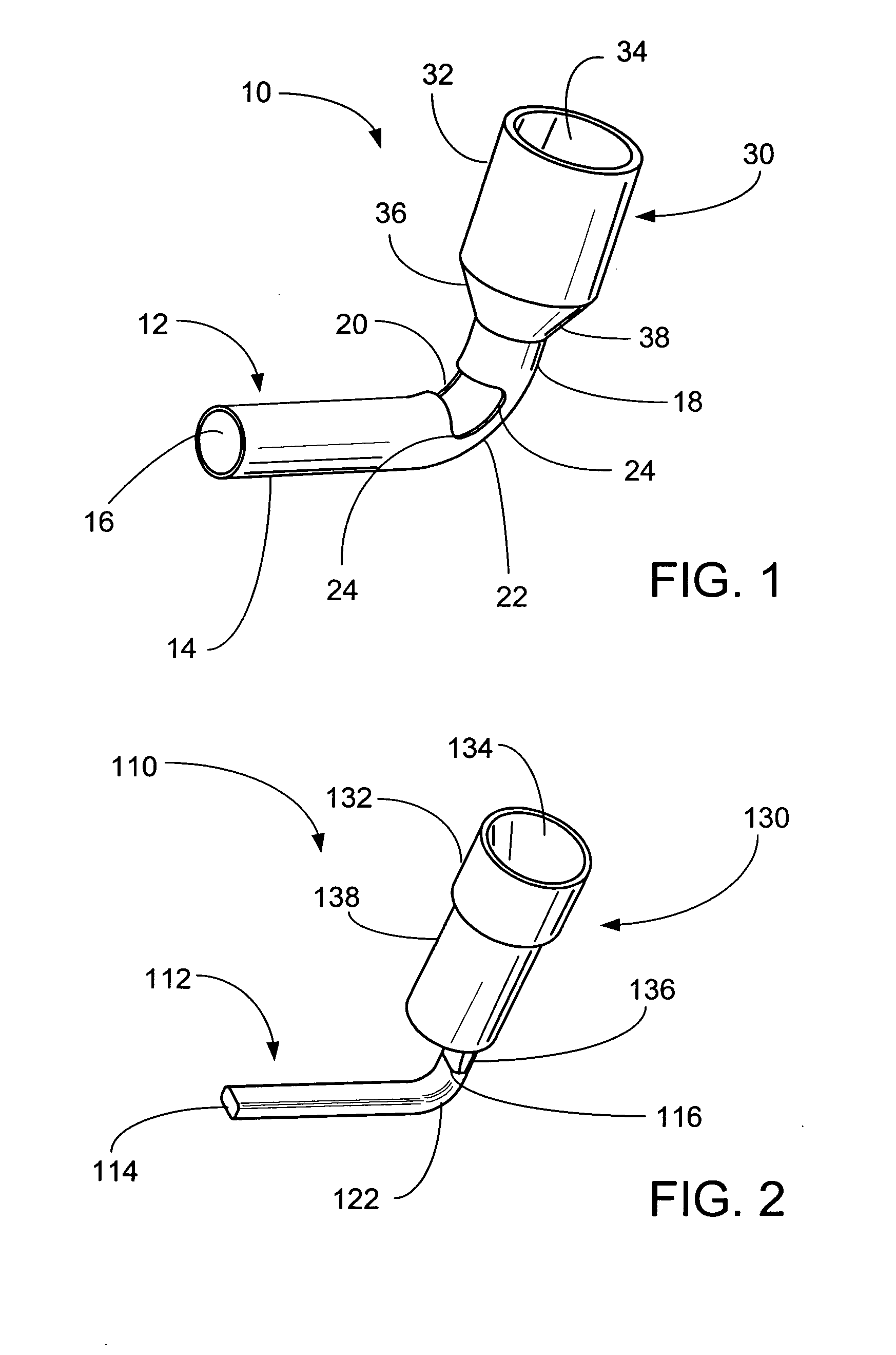
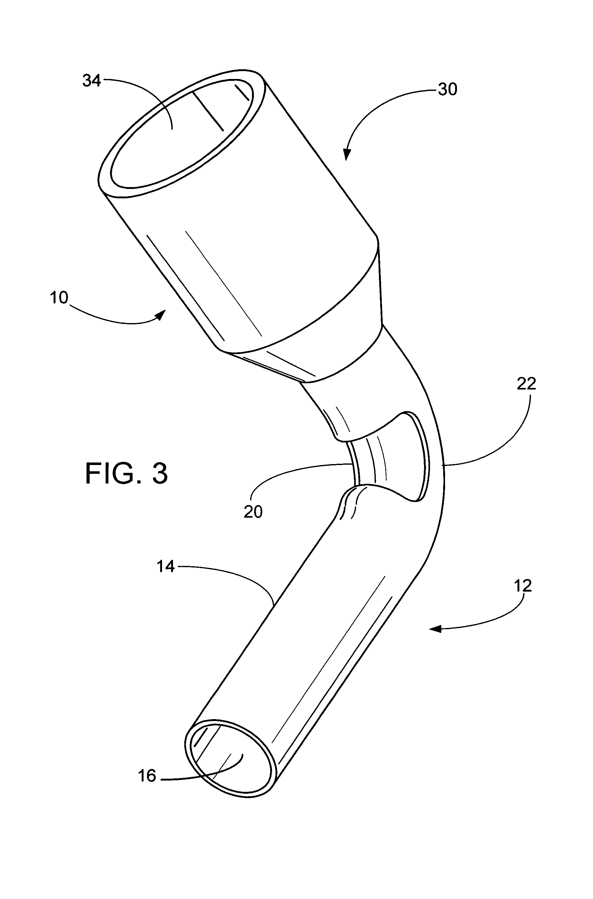
[0024]The present invention is a terminal that can have a bend of from 10-120 degrees for terminating wires to a terminal block with a ferrule or pin connection. Typically, the ferrule or pin end is connected to the terminal block and the opposing end includes an insulated sleeve for receiving the stripped end of a stranded wire. In applications where space is limited, the bends in the terminals allow them to be installed in terminal blocks from a variety of different angles.

[0025]The ferrule terminal can be bent up to about 120 degrees and includes a stress relief aperture to assist in the bending of the thin walled ferrule without creasing or damaging the outer wall. As used herein, the term “ferrule” refers to a cylindrical tube or sleeve made of a conductive metal, such as copper, and having a thin outer wall. The stranded wire is inserted through the insulated sleeve and into the ferrule. The stripped end is pushed through until it extends around the bend in the ferrule and int...


PUM


Abstract

A ferrule or pin terminal is provided with a bend to facilitate terminations in confined or restricted spaces and provides consistency and uniformity. The ferrule terminal embodiment of the present invention includes a ferrule portion and a barrel portion. The ferrule portion includes a cylindrical wall, a first end, a second end, a longitudinal axis and a stress relief aperture. The ferrule portion is bent along the longitudinal axis to form a bend. The pin terminal embodiment of the present invention includes a solid pin portion and a barrel portion. The solid pin portion includes a body, a first end and a second end and has a longitudinal axis. The first end of the solid pin portion is angularly disposed from the second end. In both embodiments, the barrel portion includes a cylindrical body having a first end adapted to receive an electrical wire and a second end connected to the second end of the ferrule.

Description

[0001]This application claims priority from provisional application Ser. No. 60 / 994,069, filed on Sep. 17, 2007, which is incorporated herein in its entirety.FIELD OF THE INVENTION[0002]The present invention relates to connectors for terminating wires. In particular, the present invention relates to 90-degree connectors for terminating wires in a confined space.BACKGROUND OF INVENTION[0003]Ferrules and pin terminals are commonly used to ensure reliable electrical connections when terminating stranded control wires in screw clamp-style terminal blocks. The primary benefit of such terminals is that they prevent fraying and breaking of wire strands, which can occur when wires are terminated directly under a terminal block screw clamp. In addition, the terminals can be insulated to provide protection from wire stress due to bending and / or vibration, while facilitating wire insertions into terminal block clamps.[0004]The trend in almost all commercial and industrial products is to reduce...

Claims


Application Information

Patent Timeline
Patent Type & Authority Applications(United States)
IPC IPC(8): H01R13/40H01R4/18
CPCH01R11/11
Inventor OSBORN, JR., ROBERT H.PRATT, MICHAEL L.
Owner THOMAS & BETTS INT INC
Why Eureka
Try Eureka