

Apparatus, method, and computer program product for rendering multi-viewpoint images
a multi-viewpoint image and computer program technology, applied in the field of picture displaying apparatus, a method, and a computer program product for rendering a multi-viewpoint image, can solve the problem of a lower rendering speed
- Summary
- Abstract
- Description
- Claims
- Application Information
AI Technical Summary
Problems solved by technology
Method used
Image

Examples
first embodiment
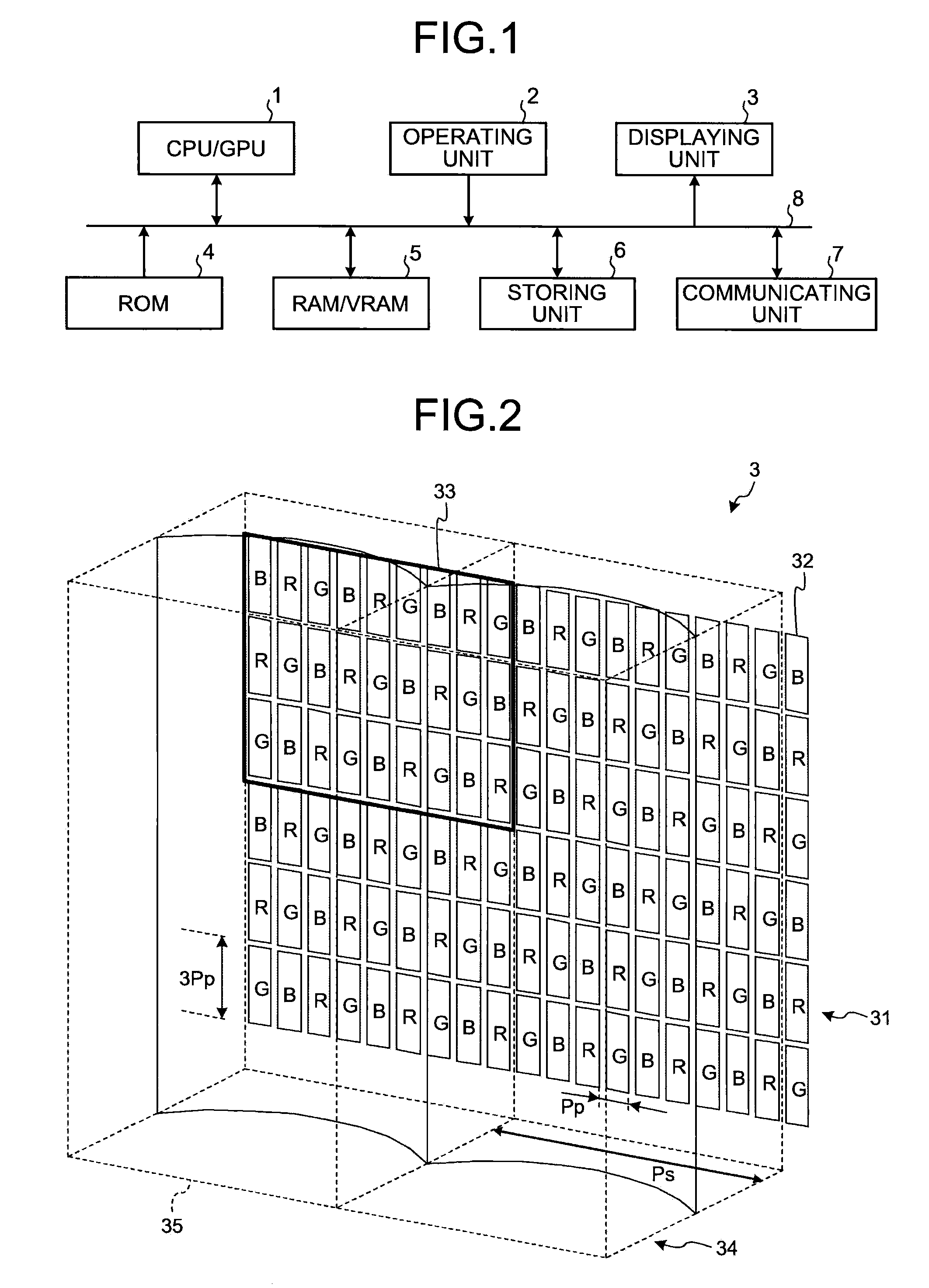
[0050]Next, a functional configuration of the multi-viewpoint image rendering apparatus 100 according to the present invention will be explained. It is assumed that the multi-viewpoint image rendering apparatus 100 has the hardware configuration as shown in FIG. 1.
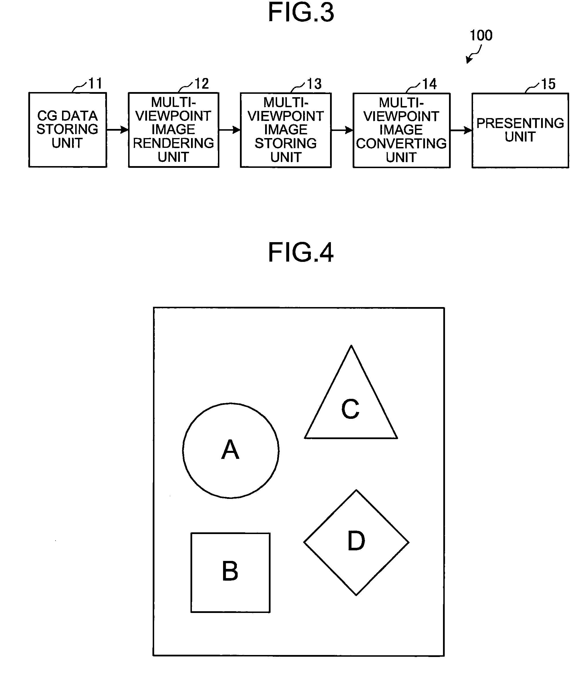
[0051]FIG. 3 is a block diagram of a functional configuration of the multi-viewpoint image rendering apparatus 100 that is realized by a collaboration of the CPU / GPU 1 and a predetermined program that is stored, in advance, in the ROM 4 or the storing unit 6. As shown in the drawing, the multi-viewpoint image rendering apparatus 100 includes a CG data storing unit 11, a multi-viewpoint image rendering unit 12, a multi-viewpoint image storing unit 13, a multi-viewpoint image converting unit 14, and the presenting unit 15.
[0052]The CG data storing unit 11 is a storage area prepared in the storing unit 6 that stores therein various types of data (hereinafter, “CG data”) that are required in a process of rendering a multi-view...
second embodiment
[0088]FIG. 13 is a block diagram of a functional configuration of a multi-viewpoint image rendering apparatus 200 according to the It is assumed that the multi-viewpoint image rendering apparatus 200 has the hardware configuration as shown in FIG. 1.
[0089]As shown in FIG. 13, in addition to the CG data storing unit 11, the multi-viewpoint image storing unit 13, the multi-viewpoint image converting unit 14, and the presenting unit 15 that have been explained above, the multi-viewpoint image rendering apparatus 200 includes a dividing method determining unit 16, a multi-viewpoint image rendering unit 17, and a partial-multi-viewpoint image storing unit 18.
[0090]Generally speaking, it has been known that the bandwidth of a memory can be a bottleneck to improve the processing speed in a CG rendering process. In the first embodiment described above, the memory bandwidth of the multi-viewpoint image storing unit 13 is not discussed; however, there is a possibility that the processing spe...
third embodiment
[0125]FIG. 22 is a block diagram illustrating a functional configuration of a multi-viewpoint image rendering apparatus 300 according to the It is assumed that the multi-viewpoint image rendering apparatus 300 has the hardware configuration as shown in FIG. 1.
[0126]As shown in FIG. 22, in addition to the multi-viewpoint image storing unit 13, the multi-viewpoint image converting unit 14, the presenting unit 15, the dividing method determining unit 16, and the partial-multi-viewpoint image storing unit 18 that have been explained above, the multi-viewpoint image rendering apparatus 300 includes a CG data storing unit 19, scene graph processing unit 20 and a multi-viewpoint image rendering unit 21.
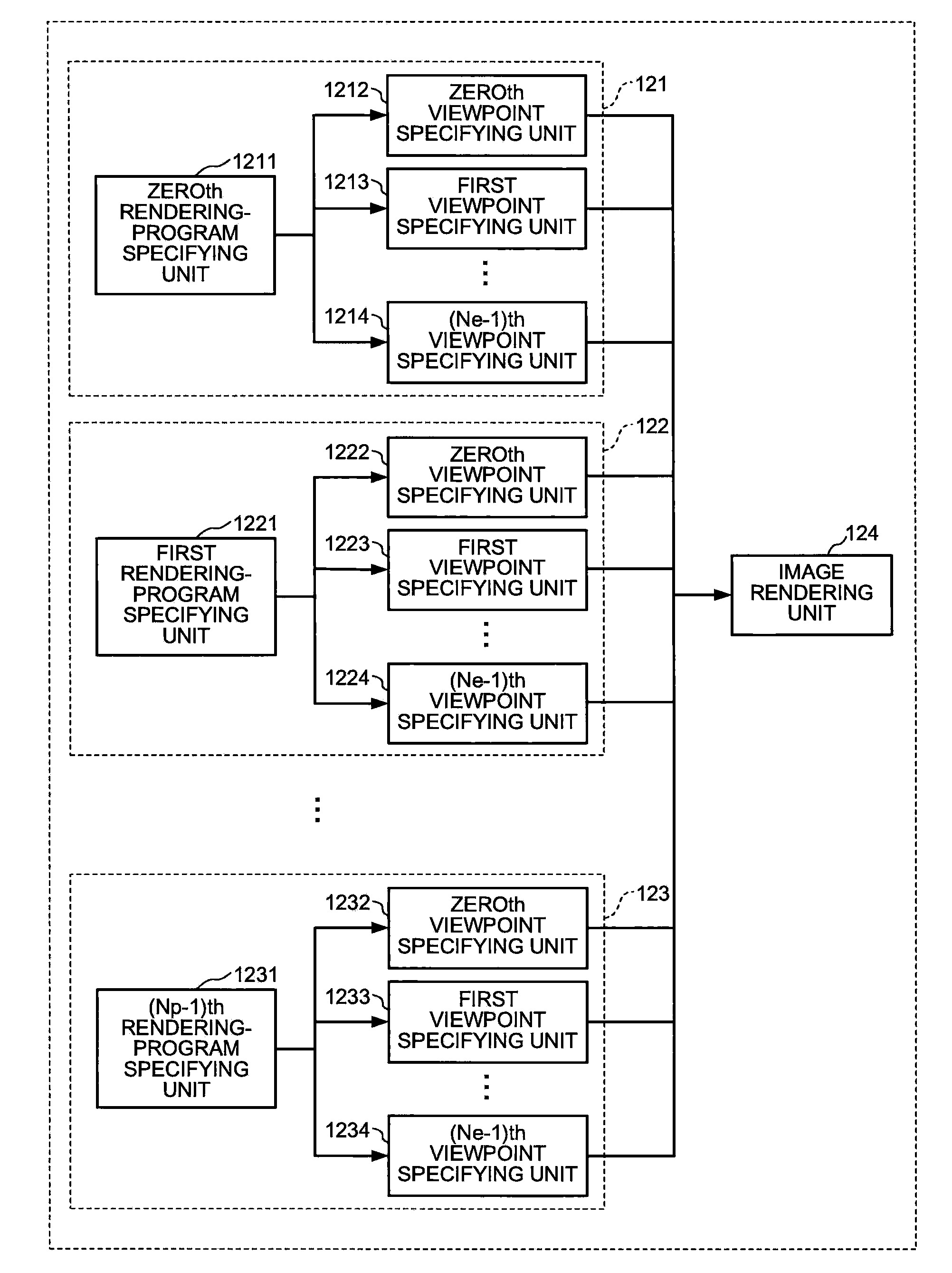
[0127]In the first and the second embodiments described above, as many rendering programs as Np are sequentially executed, starting with the one identified with the rendering program number 0 and ending with the one identified with the rendering program number Np−1. However, with an actual ...
PUM
 Abstract
Description
Claims
Application Information