
Efficient multipoint distribution tree construction for shortest path bridging

Inactive Publication Date: 2009-03-26
TELEFON AB LM ERICSSON (PUBL)
View PDF9 Cites 115 Cited by
  • Summary
  • Abstract
  • Description
  • Claims
  • Application Information

AI Technical Summary

Benefits of technology

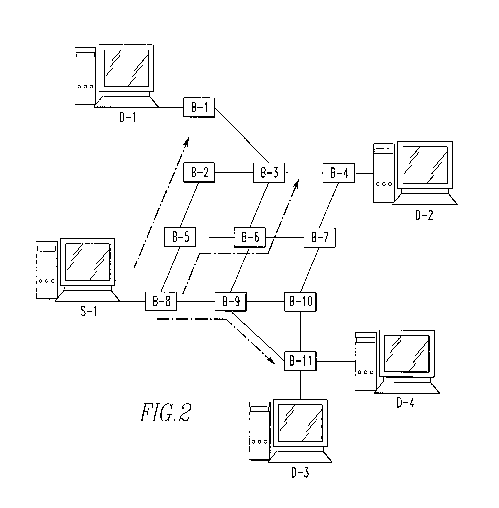
[0020]FIG. 2 is a block diagram of a simple network topology depicting the operation of the present invention.
[0021]FIG. 3 is a block diagram of a simple network topology depicting the operation of

Problems solved by technology

This approach has repeatedly been shown to have severe limitations relating to the lack of information provided by the routing protocol, and lack of support for multi-point distribution.
One issue not adequately supported by any of these approaches is the need to support Ethernet flooding, and broadcast and multicast frame distribution.
The specific issue is that multipoint distribution requires delivery to multiple points but the path used must be loop-free or frame multiplication will occur explosively (involving exponential growth at forwarding speeds).
Both of these options have severe limitations.
The most limiting issue with the first approach is the need to perform O(n2) shortest path computations at each Ethernet switch.
The most serious drawback to the second approach is the effective use of spanning tree for multipoint distribution—which:a. goes against the intent of avoiding spanning tree entirely,b. introduced the explicit need to use multiple algorithms for forwarding path determination, andc. results in divergence between forwarding paths for unicast and “multipoint” traffic.

Method used


Image

  • Efficient multipoint distribution tree construction for shortest path bridging
  • Efficient multipoint distribution tree construction for shortest path bridging
  • Efficient multipoint distribution tree construction for shortest path bridging

Examples


Embodiment Construction

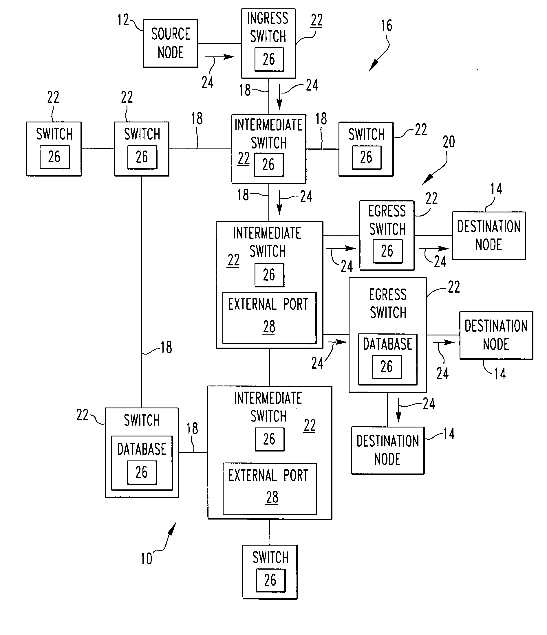
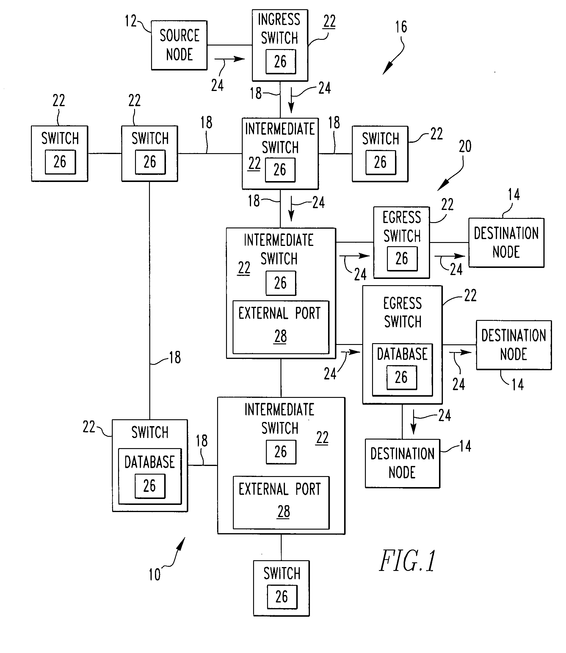
[0023]Referring now to the drawings wherein like reference numerals refer to similar or identical parts throughout the several views, and more specifically to FIG. 1 thereof, there is shown a telecommunications system 10. The system 10 comprises a source node 12. The system 10 comprises a plurality of destination nodes 14. The system 10 comprises a network 16 having links 18 and end stations 20. The system 10 comprises a plurality of switches 22 that create paths 24 along links 18 between the source nodes 12 and the destination nodes 14 where there is 100% efficiency along the paths 24 with the paths 24 traversing any link 18 only once to the corresponding destination node 14 from the source node 12, and the path 24 being a shortest path 24 between the source node 12 and the destination node 14, where each switch 22 has a Dijkstra computation complexity of O(N) in regard to forming the shortest paths 24.

[0024]Preferably, the switches 22 deliver frames from the source node 12 to the ...


PUM


Abstract

A telecommunications system includes a source node. The system includes a plurality of destination nodes. The system includes a network having links and end stations. The system includes a plurality of switches that create paths along links between the source nodes and the destination nodes where there is 100% efficiency along the paths with the paths traversing any link only once to the corresponding destination node from the source node, and the path being a shortest path between the source node and the destination node, where each switch has a Dijkstra computation complexity of O(N) in regard to forming the shortest paths. A method for telecommunications includes the steps of creating paths with a plurality of switches along links of a network between a source node and a plurality of destination nodes where there is 100% efficiency along the paths with the paths traversing any link only once to the corresponding destination node from the source node, and each path being a shortest path between the source node and the destination node, where each switch has a Dijkstra computation complexity of O(N) in regard to forming the shortest paths. There is the step of delivering with the switches frames from the source node to the destination nodes along the shortest paths.

Description

FIELD OF THE INVENTION[0001]The present invention is related to a telecommunications system that uses shortest paths where there is 100% efficiency along the paths with the paths traversing any link only once. More specifically, the present invention is related to a telecommunications system that uses shortest paths where there is 100% efficiency along the paths with the paths traversing any link only once by computing the shortest point to point path from a source node to each destination node, and each switch forms shortest point to multipoint paths from the source node to the destination nodes without additional shortest path computations from the shortest point to point paths.BACKGROUND OF THE INVENTION[0002]Currently existing technologies use spanning tree for unicast, multicast and broadcast delivery of Ethernet frames (or protocol data units—PDUs).[0003]In development proposals have suggested (for many years) the use of shortest path construction using a (potentially modified...

Claims


Application Information

Patent Timeline
IPC IPC(8): H04L12/28
CPCH04Q3/66H04Q2213/13056H04Q2213/13389H04Q2213/13141H04Q2213/13242H04Q2213/13138
Inventor GRAY, ERIC WARD
Owner TELEFON AB LM ERICSSON (PUBL)
Learn More