
Printing machine

Inactive Publication Date: 2009-03-26
MITSUBISHI HEAVY IND LTD
View PDF1 Cites 0 Cited by
  • Summary
  • Abstract
  • Description
  • Claims
  • Application Information

AI Technical Summary

Benefits of technology

[0024]On the other hand, if a panel is fixed to a printing unit by screws or nuts, such screws need to be removed upon replacement of the panel. Therefore, replacement of the panel is cumbersome, and takes a long time. Besides, such a screw may drop during the operation and damage other units. Moreover, such screws impair the appearance of a printing unit. Furthermore, it is difficult to remove dirt on a portion where a screw is arranged upon cleaning the panel, making it difficult to clean a printing press.

Problems solved by technology

Therefore, the replacement of a panel is cumbersome and takes a long time.

Method used


Image

  • Printing machine
  • Printing machine
  • Printing machine

Examples


Embodiment Construction

[0016]Exemplary embodiments of the present invention are explained in detail below with reference to the accompanying drawings.

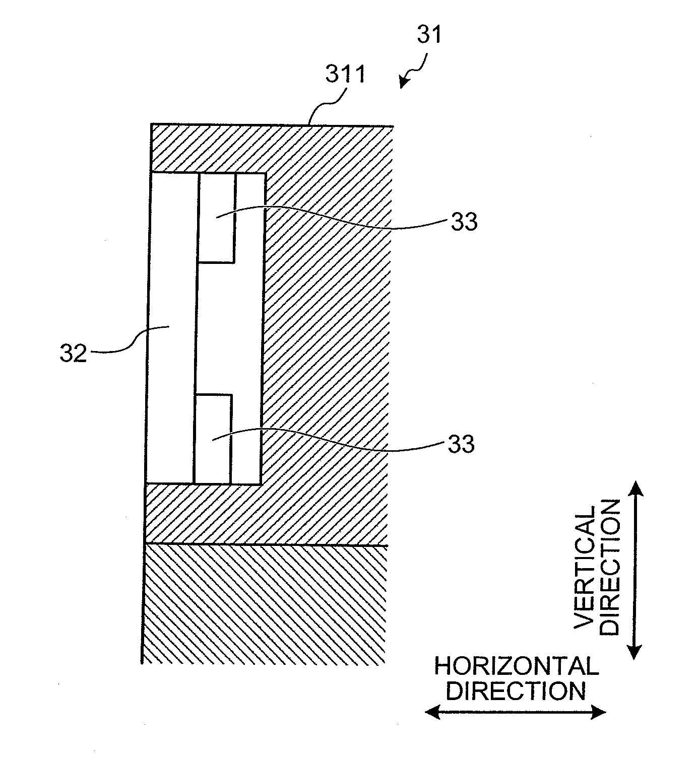
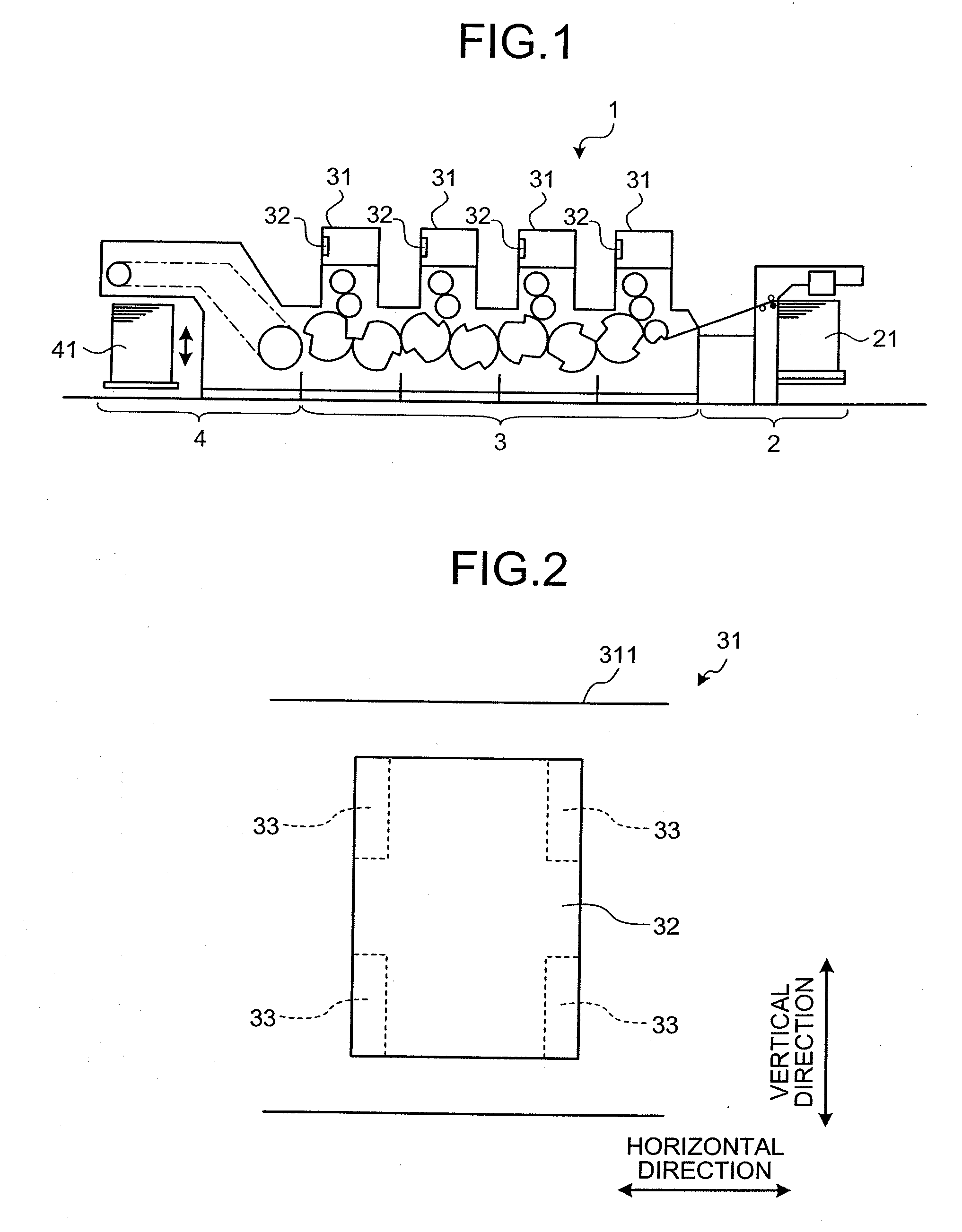
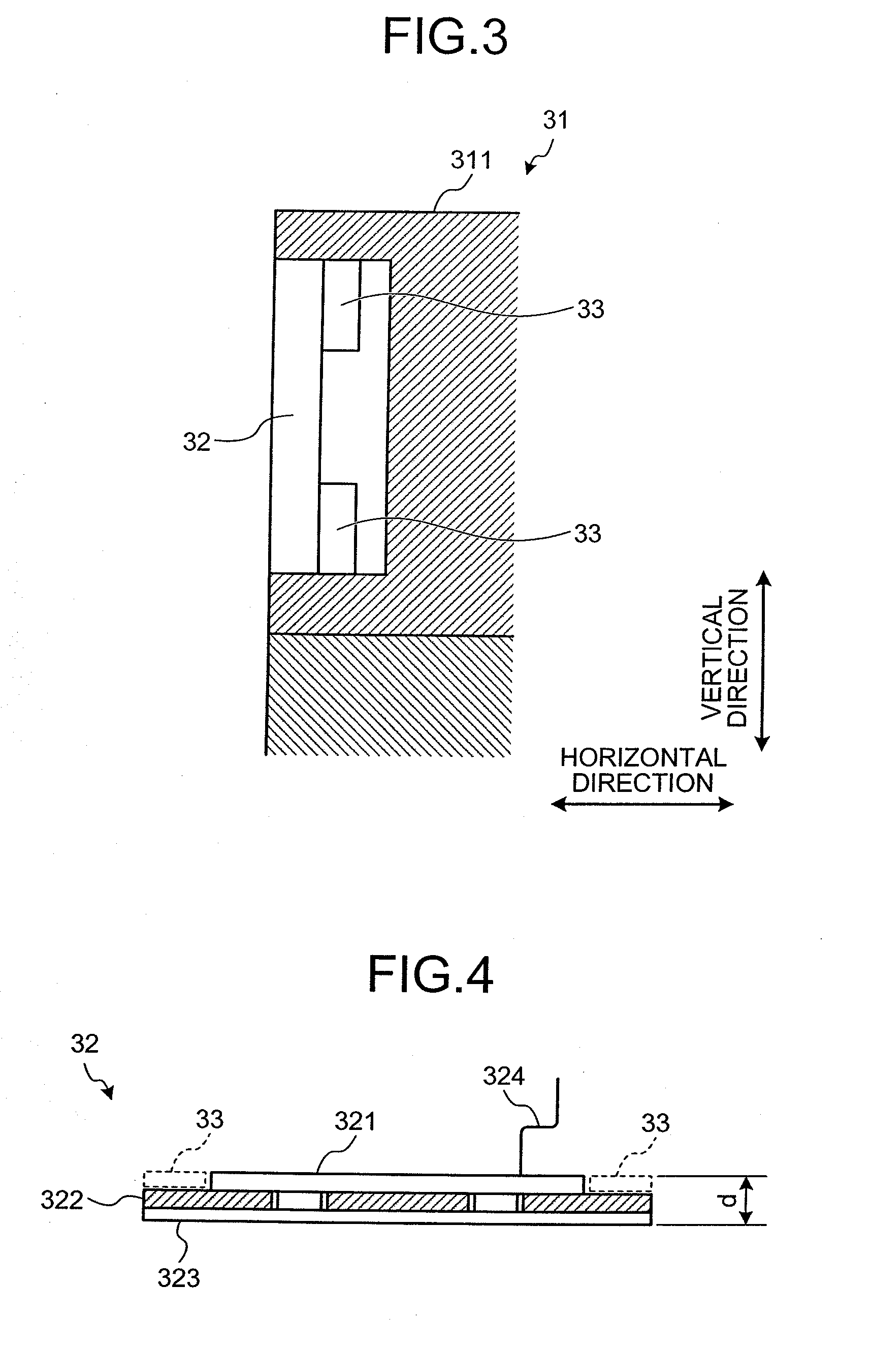
[0017]FIG. 1 is a schematic diagram of a printing press 1 according to an embodiment of the present invention. The printing press 1 is, for example, a sheet-fed printing press, and includes a feed mechanism 2, a printing mechanism 3, and a delivery mechanism 4 (see FIG. 1). The feed mechanism 2 includes a feeder unit 21. The feeder unit 21 picks up a sheet set for printing, and feeds the sheet to the printing mechanism 3. Specifically, a plurality of sheets are stacked and set in the feeder unit 21, and each of the sheets is sequentially picked up and fed to the printing mechanism 3. The printing mechanism 3 includes a plurality of the printing units 31. The printing units 31 correspond to four different colors of C (cyan), M (magenta), Y (yellow), and BL (black), respectively, and aligned along a path for conveying a sheet S. The printing mechanism 3 perfor...


PUM


Abstract

A printing press includes a printing unit, a feeder unit, and a delivery unit. At least one of the units is provided with a panel for either or both operating the unit and displaying the state of the unit. The panel is attached to the unit with a magnet, and is held by the attractive force of the magnet.

Description

BACKGROUND OF THE INVENTION[0001]1. Field of the Invention[0002]The present invention relates to a printing press.[0003]2. Description of the Related Art[0004]Printing machines developed in recent years include a printing unit equipped with an operation panel (hereinafter, “panel”) for controlling the printing unit.[0005]Japanese Patent Application Laid-Open No. H11-291462 discloses a conventional technology related to such a printing press (gravure printing press). The printing press includes a plurality of printing units arranged at a predetermined interval. Each of the printing units includes a printing mechanism that includes a cylinder and various printing auxiliaries, and a control operation unit of the printing mechanism. In the printing press, the printing mechanism is arranged in such a manner that the longitudinal side of the printing mechanism is orthogonal to a direction of arrangement of the printing unit. The control operation unit is arranged on an end portion of the ...

Claims


Application Information

Patent Timeline
IPC IPC(8): B41J29/02
CPCB41F13/0024
Inventor MORIMOTO, SATOSHIMATSUURA, YOSHIRO
Owner MITSUBISHI HEAVY IND LTD
Learn More