

Modular hemofiltration apparatus with removable panels for multiple and alternate blood therapy
a hemofiltration apparatus and hemofiltration technology, applied in the field of modular hemofiltration apparatus with re, can solve the problems of inconvenient and time-consuming setup procedures for extracorporeal blood treatment apparatus, and achieve the effect of quick and efficient change of therapy, easy installation and replacemen
- Summary
- Abstract
- Description
- Claims
- Application Information
AI Technical Summary
Benefits of technology
Problems solved by technology
Method used
Image

Examples
Embodiment Construction
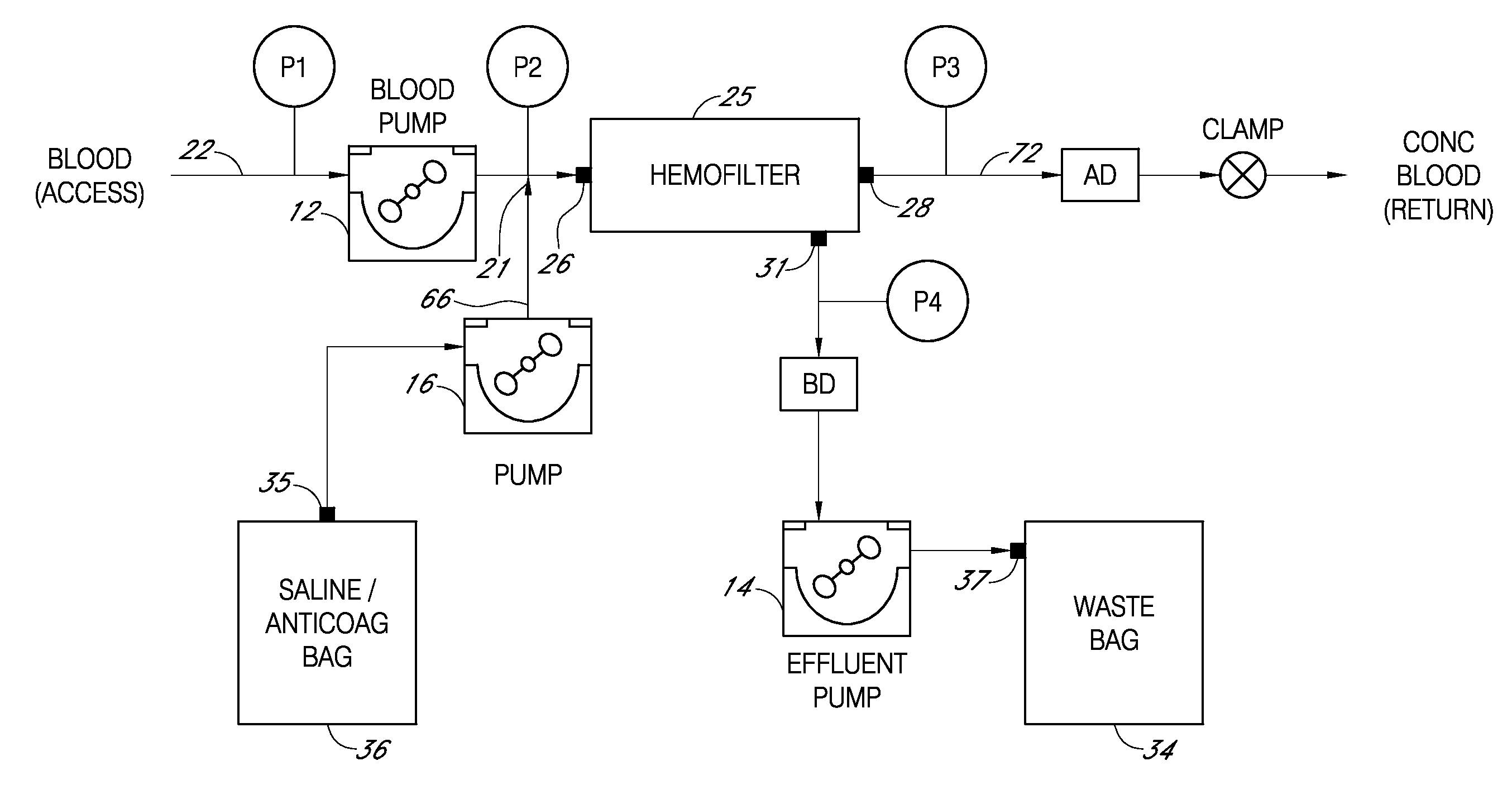
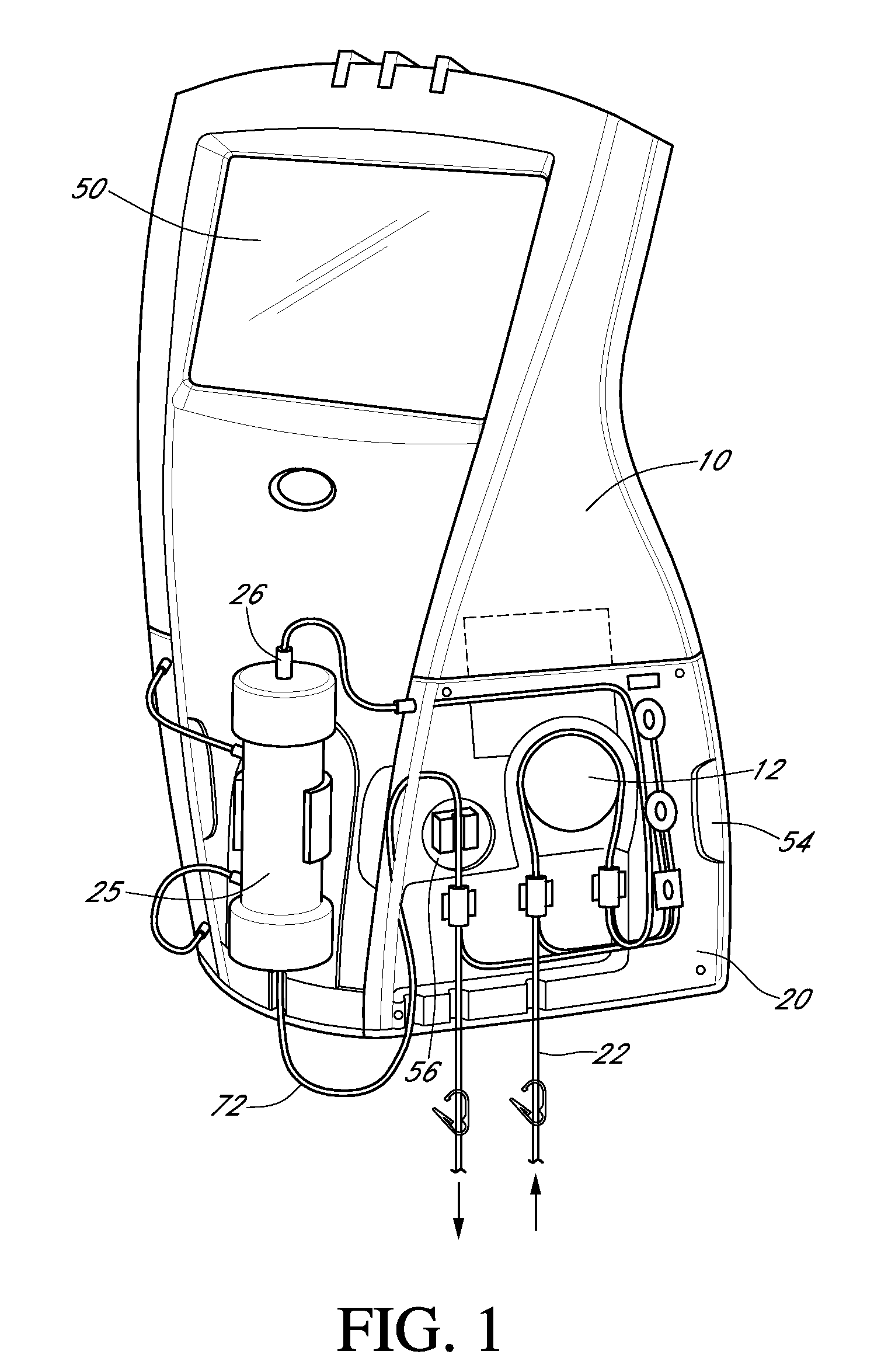
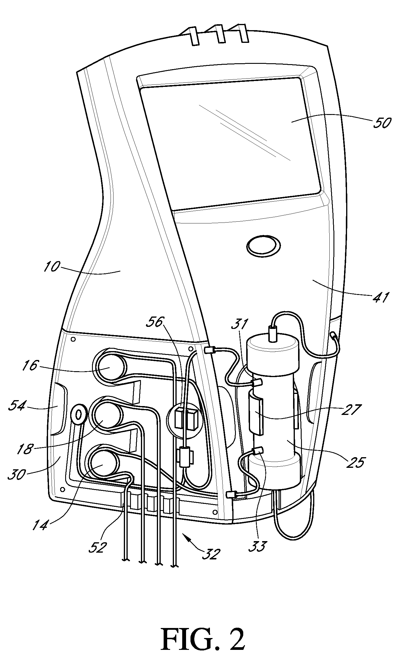
[0013]It is understood that different patients have different medical conditions that require a selected therapy, or multiple or alternating therapies. Such different therapies may also call for use of different filter cartridges or columns as well as different tubing routing and setups. Moreover, there may be a need to exchange filter cartridges or columns during a procedure if the cartridge has failed or has become clogged.
[0014]The apparatus described herein is designed for convenient setup to provide CRRT selection as well as plasma separation, plasma exchange (TPE) and plasma treatment, such as therapeutic apheresis (TA), and thereafter, if desired, efficiently and economically modify the apparatus configuration to carry out a different blood therapy or plasma treatment. A blood tubing panel and fluid tubing panels are provided with identification components which are sensed or read by the computer / controller capable of reading and identifying which tubing panel and filter colu...
PUM
| Property | Measurement | Unit |
|---|---|---|
| time | aaaaa | aaaaa |
| weights | aaaaa | aaaaa |
| surface area | aaaaa | aaaaa |
Abstract
Description
Claims
Application Information