Path testing and switching

a path testing and switching technology, applied in the field of network communication and path testing, can solve the problems of failure of links connecting various network devices, network devices often experiencing congestion related problems, and data routing in a network has become increasingly complex,

Active Publication Date: 2009-04-02
VERIZON PATENT & LICENSING INC
View PDF11 Cites 98 Cited by
  • Summary
  • Abstract
  • Description
  • Claims
  • Application Information

AI Technical Summary

Problems solved by technology

Routing data in a network has become increasingly complex due to increased overall traffic and customer bandwidth requirements.
As a result, network devices often ex

Method used


Image

  • Path testing and switching
  • Path testing and switching
  • Path testing and switching

Examples


Embodiment Construction

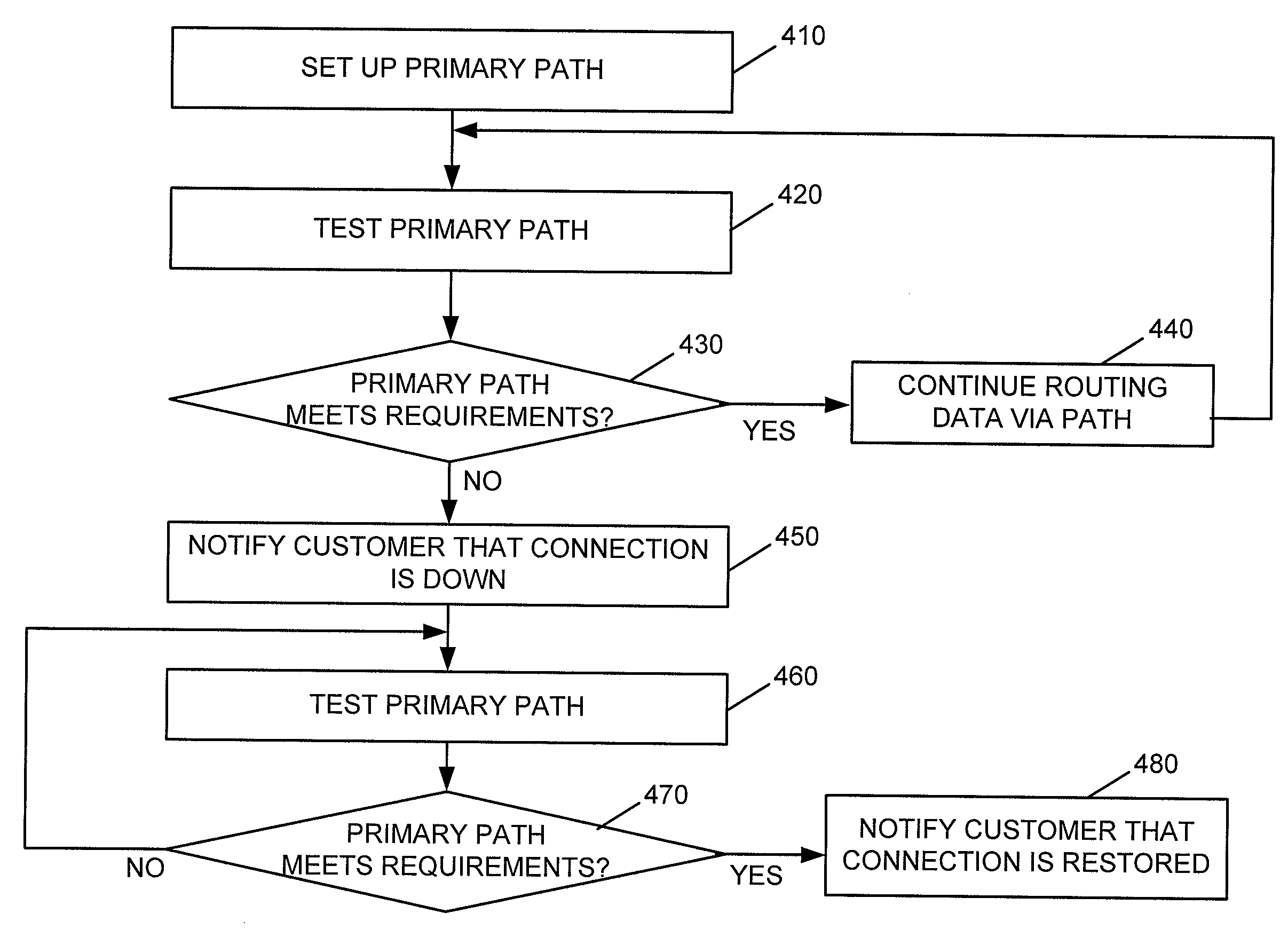
[0007]The following detailed description refers to the accompanying drawings. The same reference numbers in different drawings may identify the same or similar elements. Also, the following detailed description does not limit the invention. Instead, the scope of the invention is defined by the appended claims and their equivalents.

[0008]Implementations described herein relate to network communications and path switching. When a primary path associated with routing a customer's data experiences problems, such as latency-related problems, the customer may be notified that the path does not satisfy the customer's particular requirements. In some implementations, traffic may be re-routed on an alternate path that satisfies the customer's particular requirements.

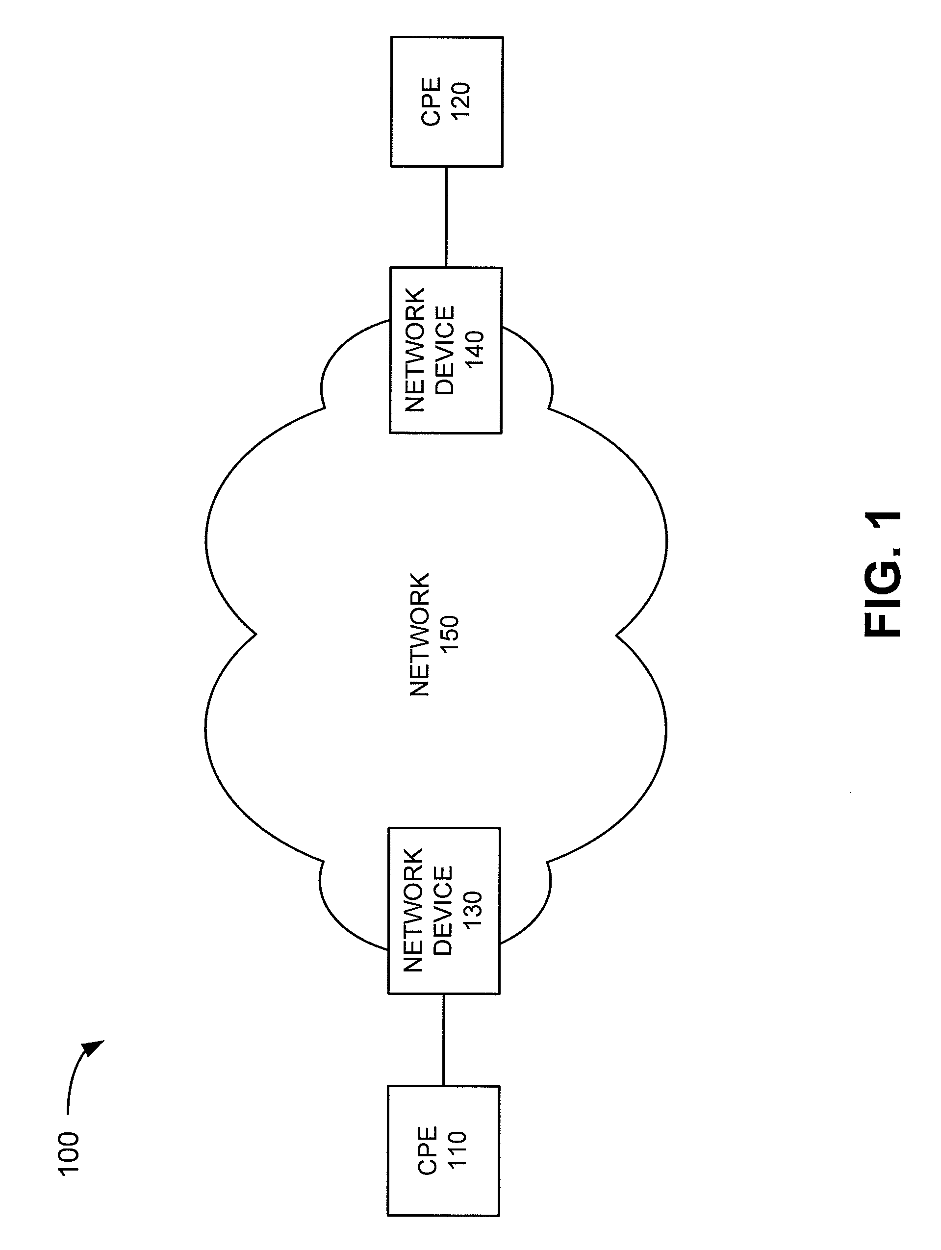
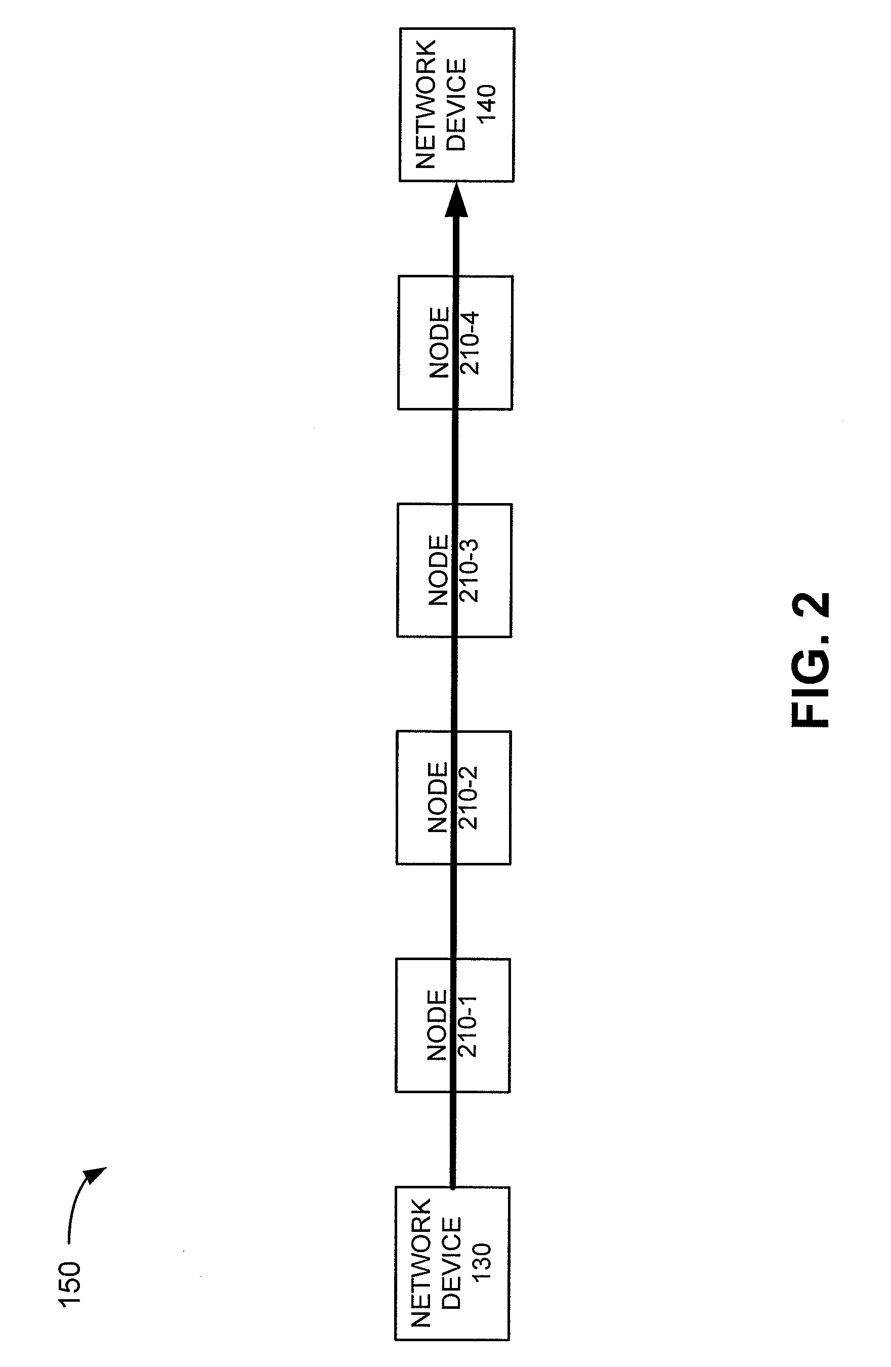
[0009]FIG. 1 is a block diagram of an exemplary network 100 in which systems and methods described herein may be implemented. Network 100 may include customer premises equipment (CPE) 110, CPE 120, network device 130, network dev...


PUM


Abstract

A method may include forming a first path from a first node to a second node and transmitting data via the first path. The method also includes measuring a performance parameter associated with transmitting data via the first path and determining whether the measured performance parameter meet a required performance parameter. The method also includes sending a notification to a customer associated with the first path when the measured performance parameter does not meet the required performance parameter, where the notification indicates that the first path is unavailable.

Description

BACKGROUND INFORMATION[0001]Routing data in a network has become increasingly complex due to increased overall traffic and customer bandwidth requirements. As a result, network devices often experience congestion related problems, such as latency problems, and may also fail. Links connecting various network devices may also experience problems and / or fail.BRIEF DESCRIPTION OF THE DRAWINGS[0002]FIG. 1 illustrates an exemplary network in which systems and methods described herein may be implemented;[0003]FIG. 2 illustrates an exemplary configuration of a portion of the network of FIG. 1;[0004]FIG. 3 illustrates an exemplary configuration of a network device of FIG. 1;[0005]FIG. 4 is a flow diagram illustrating exemplary processing by various devices illustrated in FIG. 1; and[0006]FIG. 5 illustrates the routing of data via a path in the portion of the network illustrated in FIG. 2.DETAILED DESCRIPTION OF PREFERRED EMBODIMENTS[0007]The following detailed description refers to the accom...

Claims


Application Information

Patent Timeline
IPC IPC(8): H04J3/14
CPCH04L41/5038H04L41/507H04L43/0852H04L43/16H04L45/50H04L45/02H04L45/22H04L45/28H04L45/00H04L43/55
Inventor KOTRLA, SCOTT R.DEL REGNO, CHRISTOPHER N.TURLINGTON, MATTHEW W.BENCHECK, MICHAEL U.SCHELL, RICHARD C.
Owner VERIZON PATENT & LICENSING INC
Why Eureka
Try Eureka