Orthopedic device assembly with elements coupled by a retaining structure

a technology of orthopedic devices and retaining structures, which is applied in the field of orthopedic devices having elements, can solve the problems that the degenerative disc disease (ddd) may become inconvenient to non-surgical treatment and have to be treated

Active Publication Date: 2009-04-02
K2M
View PDF12 Cites 78 Cited by
  • Summary
  • Abstract
  • Description
  • Claims
  • Application Information

AI Technical Summary

Benefits of technology

[0021]The retaining element of angular cross-section has a base or back portion that forms one arm of the angular or L-shape and is received and confined within the retaining groove. The axial extent of the base or back portion has a first region that is confined within the retaining groove by contact with the outer wall of the interior element and a second region provided with a flange portion projecting outwardly of the groove. The flange portion engages the interior element of the assembly, e.g., by overhanging a shoulder thereof or fitting into a groove in the outer wall thereof to constrain axial movement of the interior element. The retaining element has particular utility in coupling an elastomeric core element of an intervertebral prosthesis to an endplate thereof as described below.

Problems solved by technology

Such degenerative disc disease (DDD) may become intractable to non-surgical treatment and have to be treated by surgical intervention.

Method used


Image

  • Orthopedic device assembly with elements coupled by a retaining structure
  • Orthopedic device assembly with elements coupled by a retaining structure
  • Orthopedic device assembly with elements coupled by a retaining structure

Examples


Embodiment Construction

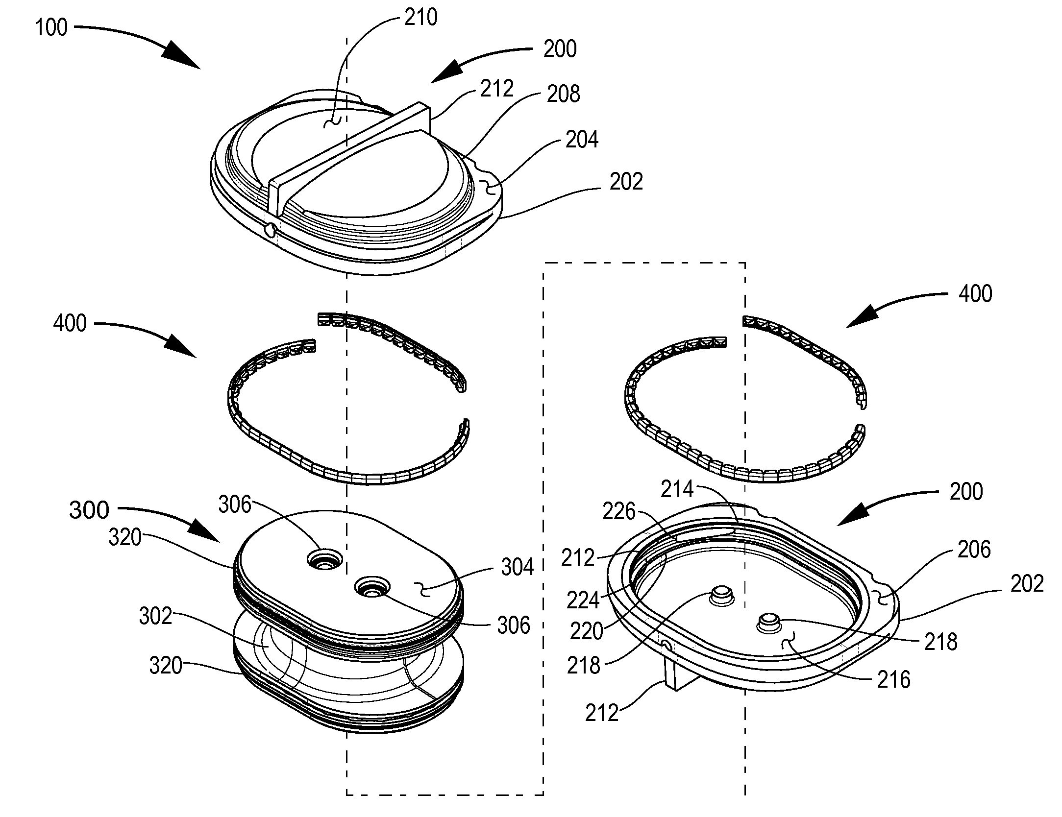
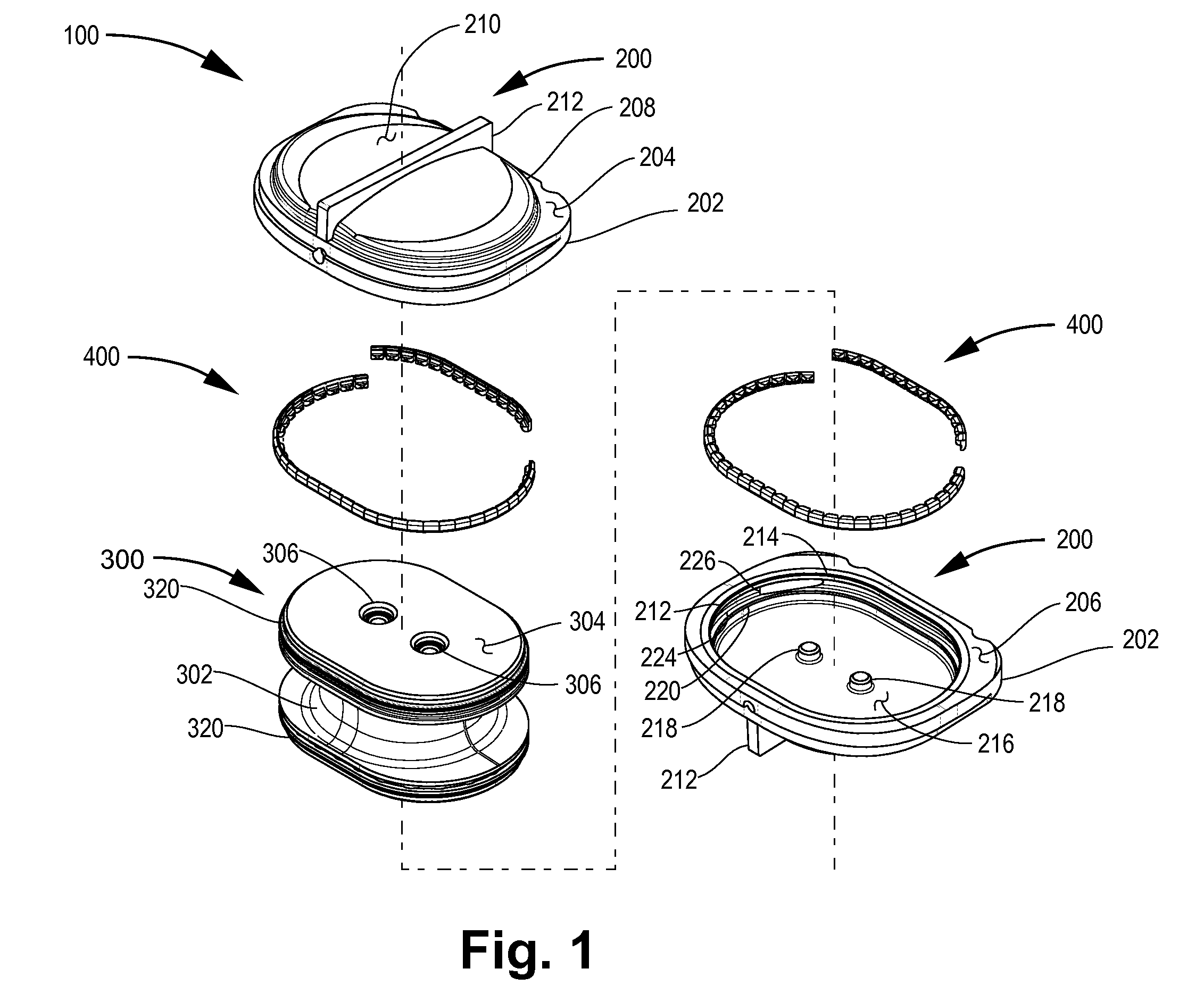
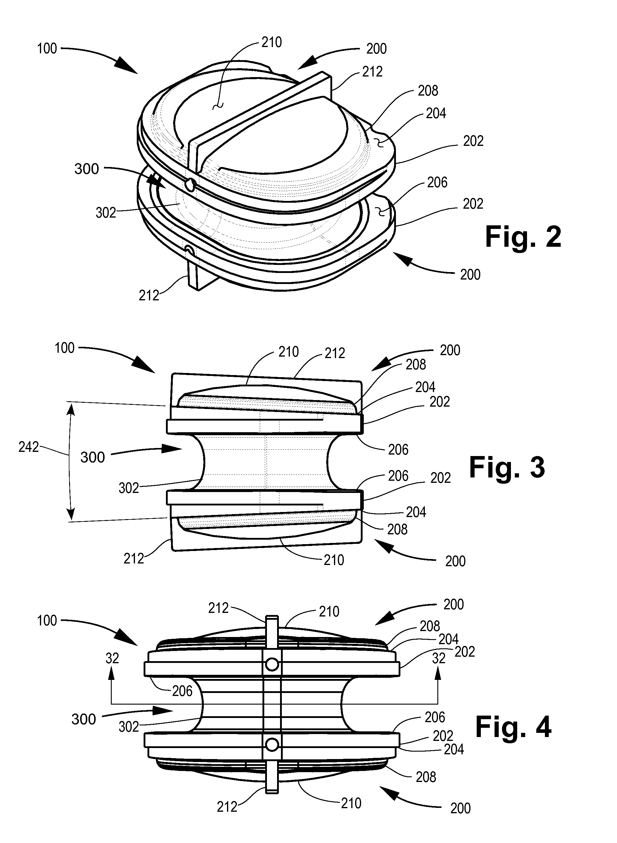
[0060]When an injured, degenerated, or otherwise defective intervertebral disc has to be surgically replaced, the surgeon excises the pathological disc, or a portion thereof, and inserts in its place a prosthesis of appropriate size and shape. The cross-sectional size of the disc to be replaced, as well as the relative angle of orientation between the adjacent vertebrae, will, in general, vary, depending on the stature of an individual patient and the location within the spinal column of the intervertebral disc to be replaced. Accordingly, a variety of prostheses, having different cross-sectional sizes, with vertebra-contacting surfaces set at different angles, must be available to the surgeon in order to provide a proper fit of the prosthesis within the intervertebral space.

[0061]The invention makes it possible to construct intervertebral prostheses having a wide variation in cross-sectional size and endplate angles from a relatively small number of components. Typically, an elasto...


PUM

PropertyMeasurementUnit
lordotic angleaaaaaaaaaa
lordotic anglesaaaaaaaaaa

Abstract

The present invention provides an orthopedic device assembly comprising a first assembly element, a second assembly element, and a retaining mechanism. The first assembly element has a recess that receives the second assembly element, and the retaining mechanism holds the second element in an assembled state with the first assembly element. The retaining mechanism includes a retaining member with an angular cross-section defined by a base portion and a lateral flange portion projecting from the base portion. The retaining member is inserted through an aperture of the first assembly element into a groove in a wall of the recess of the first assembly element, with the flange portion projecting laterally of the groove and overhanging a shoulder portion of the second assembly element so as to retain the second assembly element in the assembled state with the first assembly element.

Description

CROSS-REFERENCE TO RELATED APPLICATIONS[0001]This application claims the benefit of U.S. Provisional Application No. 60 / 975,766, filed Sep. 27, 2007, the entire disclosure of which is incorporated herein by reference, and the benefit of U.S. Provisional Application No. 61 / 050,554, filed May 5, 2008, the entire disclosure of which is incorporated herein by reference.BACKGROUND OF THE INVENTION[0002]1. Field of the Invention[0003]This invention relates to orthopedic devices having elements which are coupled by a retaining mechanism.[0004]2. Background Art[0005]Low back pain is a very common pathological condition, affecting approximately 80% of the general population at some time. Although most patients experience the painful symptoms only occasionally and recover fully, approximately 10% of these patients come to experience chronic and disabling low back pain in spite of various medical treatments.[0006]The most common cause of chronic disabling low back pain is degeneration of one o...

Claims


Application Information

Patent Timeline
Patent Type & Authority Applications(United States)
IPC IPC(8): A61F2/44
CPCA61F2/442A61F2/4611A61F2002/3013A61F2002/30492A61F2002/30495Y10T29/49826A61F2002/30604A61F2002/30884A61F2220/0025A61F2220/0033A61F2230/001A61F2002/30563
Inventor OGILVIE, WILLIAM F.MAKRIS, GEORGE
Owner K2M
Why Eureka
Try Eureka