Method for making a metal-backed acetabular implant

a technology of acetabular implants and metal backings, applied in the field of orthopaedics, can solve the problems of degrading the biomechanics and/or wear characteristics of conventional hip prosthesis, and balancing the needs for effective bearing retention with competing desires for design simplicity and versatility

Inactive Publication Date: 2009-04-02
ZIMMER TECH INC
View PDF50 Cites 159 Cited by
  • Summary
  • Abstract
  • Description
  • Claims
  • Application Information

AI Technical Summary

Problems solved by technology

A substantial dislocation and / or rotation of the bearing relative to the shell can potentially degrade the biomechanics and / or wear characteristics of the conventional hip prosthesis.
Historically, balancing the needs for effective bearing retention with competing desires for design simplicity and versatility has been challenging.

Method used


Image

  • Method for making a metal-backed acetabular implant
  • Method for making a metal-backed acetabular implant
  • Method for making a metal-backed acetabular implant

Examples


Embodiment Construction

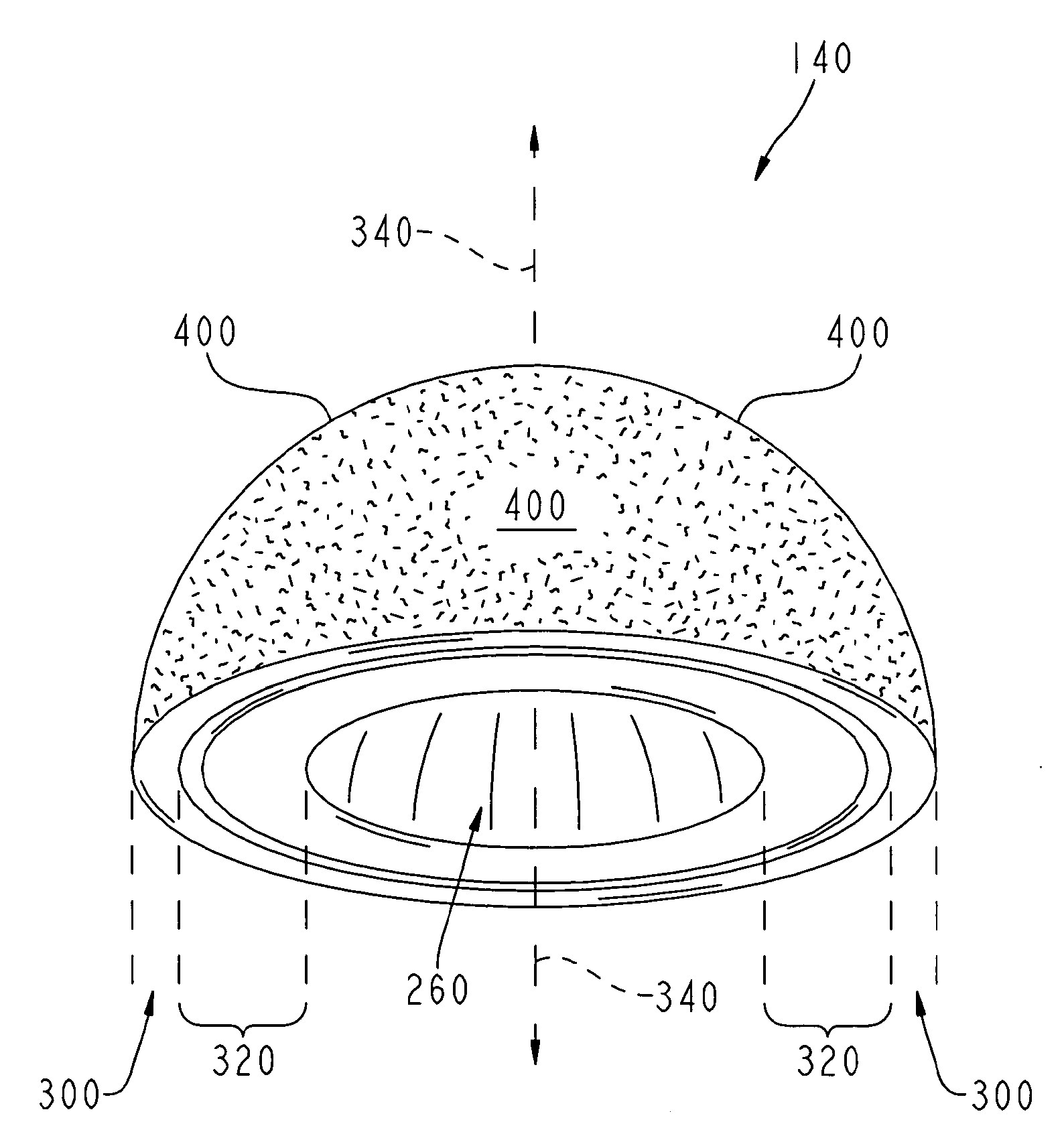
[0020]Like reference numerals refer to like parts throughout the following description and the accompanying drawings. As used herein, the terms “medial,”“medially,” and the like mean pertaining to the middle, in or toward the middle, and / or nearer to the middle of the body when standing upright. Conversely, the terms “lateral,”“laterally,” and the like are used herein as opposed to medial. For example, the medial side of the knee is the side closest to the other knee and the closest sides of the knees are medially facing, whereas the lateral side of the knee is the outside of the knee and is laterally facing. Further, as used herein the term “superior” means closer to the top of the head and / or farther from the bottom of the feet when standing upright. Conversely, the term “inferior” is used herein as opposed to superior. For example, the heart is superior to the stomach and the superior surface of the tongue rests against the palate, whereas the stomach is inferior to the heart and...


PUM

PropertyMeasurementUnit
molecular weightaaaaaaaaaa
angleaaaaaaaaaa
distanceaaaaaaaaaa

Abstract

A metal-backed acetabular implant and a method of forming the same.

Description

CROSS REFERENCE TO RELATED APPLICATION[0001]This application is a continuation of U.S. patent application Ser. No. 11 / 104,974, entitled “Method for Making a Metal-Backed Acetabular Implant,” filed on Apr. 12, 2005 by the same inventor hereof, the disclosure of which is expressly incorporated herein by reference.BACKGROUND[0002]1. Field of the Invention[0003]The present invention relates generally to the field of orthopaedics, and, more particularly, to a method of making a metal-backed acetabular implant for a hip prosthesis.[0004]2. Description of the Related Art[0005]A conventional hip prosthesis is primarily composed of an acetabular implant and a femoral implant. The acetabular implant typically includes a generally hemispherical dome-like or cup-like metallic shell secured within the acetabulum and a dome-like or cup-like plastic or ceramic bearing secured within the shell. Accordingly, the shell typically includes an exterior configured to be anchored into the acetabulum and f...

Claims


Application Information

Patent Timeline
Patent Type & Authority Applications(United States)
IPC IPC(8): A61F2/32B23P11/00
CPCA61F2/30767Y10T29/49826A61F2/3094A61F2/32A61F2/34A61F2/36A61F2/3662A61F2/4637A61F2002/30345A61F2002/30378A61F2002/30487A61F2002/30542A61F2002/30612A61F2002/30906A61F2002/30957A61F2002/3411A61F2002/3437A61F2002/3448A61F2002/3451A61F2002/3611A61F2002/4654A61F2220/0025A61F2220/0033A61F2310/00023A61F2310/00029B29C43/003B29L2031/7532A61F2/30771A61F2002/305A61F2002/3054A61F2002/30604A61F2002/4653
Inventor CASE, KIRT L.
Owner ZIMMER TECH INC
Why Eureka
Try Eureka