
Method and apparatus for automatically identifying potentially unsafe work conditions to predict and prevent the occurrence of workplace accidents

a technology of work conditions and automatic identification, applied in the field of data processing systems, can solve problems such as loss of production, loss of profits, injury or even death, and ineffective rules for preventing workplace accidents

Inactive Publication Date: 2009-04-02
IBM CORP
View PDF89 Cites 94 Cited by
  • Summary
  • Abstract
  • Description
  • Claims
  • Application Information

AI Technical Summary

Problems solved by technology

Workplace accidents may include, for example, an explosion at a chemical plant, a release of chemicals or toxins into the environment, injury to one or more workers, or any other event that disrupts the processes occurring at the workplace location.
Consequences of workplace accidents may include loss of production, loss of equipment, loss of profit, injury or even loss of life.
Workplace accidents may be caused by a complex set of actions, events, or omissions that can be attributed to worker inattentiveness, carelessness, or lack of experience and training.
However, these rules are ineffective for preventing workplace accidents that result from otherwise undetectable or unexpected conditions or events.
This costly and time consuming process often requires the investigators to reconstruct the accident scene, analyze production data, perform detailed interviews of witnesses to the accident, and complete a long checklist of tasks in order to deduce the cause of the accident.
In some instances, the accident cannot be reconstructed because the clues to the cause of the accident have been destroyed, or because participants or witnesses cannot clearly recall the actions and events leading up to the workplace accident.
Thus, the cause of the workplace accident may never be identified and the workplace accident may recur at some point in the future.

Method used


Image

  • Method and apparatus for automatically identifying potentially unsafe work conditions to predict and prevent the occurrence of workplace accidents
  • Method and apparatus for automatically identifying potentially unsafe work conditions to predict and prevent the occurrence of workplace accidents
  • Method and apparatus for automatically identifying potentially unsafe work conditions to predict and prevent the occurrence of workplace accidents

Examples


Embodiment Construction

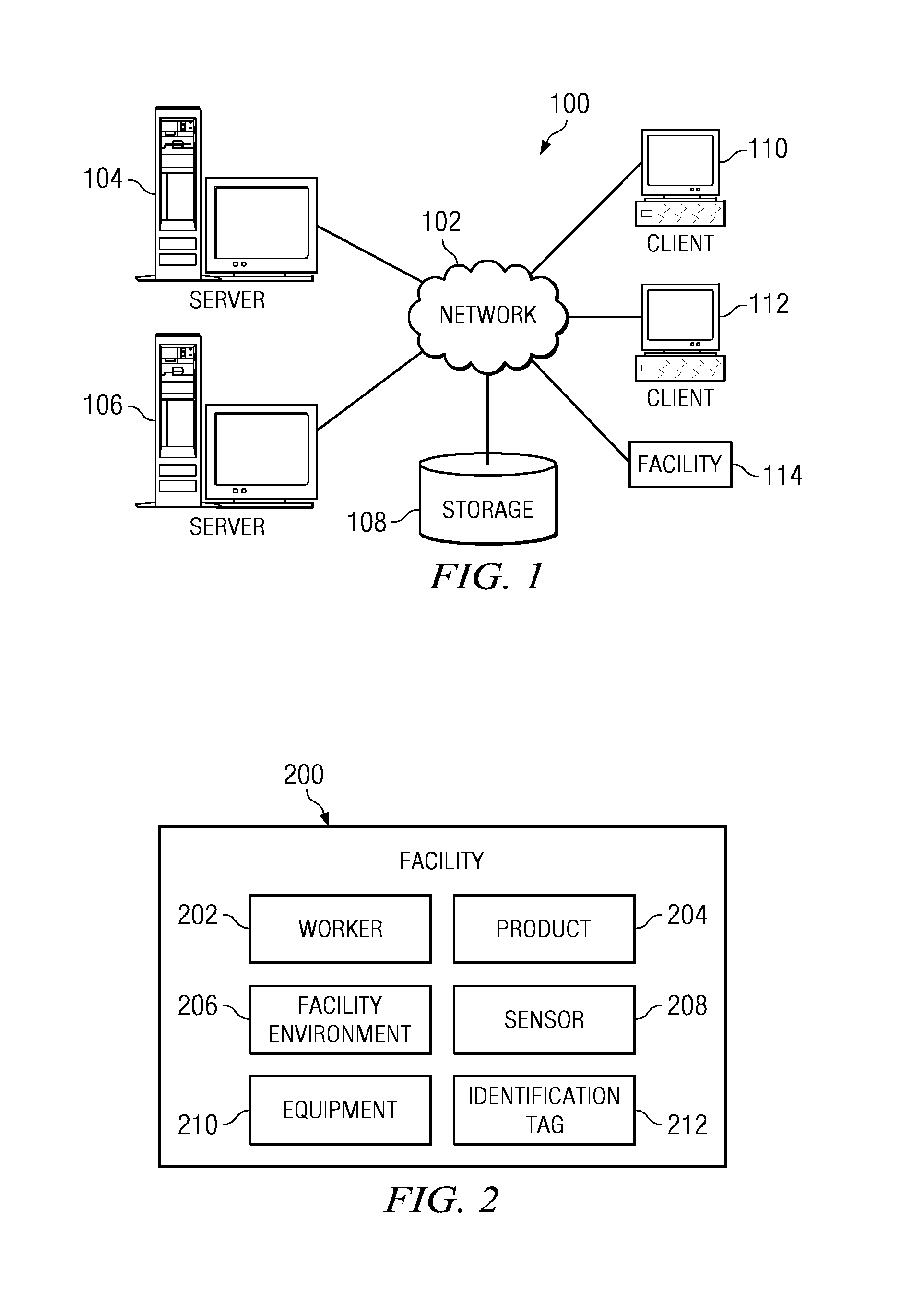
[0019]With reference now to the figures, and in particular, with reference to FIGS. 1-2, exemplary diagrams of data processing environments are provided in which illustrative embodiments may be implemented. It should be appreciated that FIGS. 1-2 are only exemplary and are not intended to assert or imply any limitation with regard to the environments in which different embodiments may be implemented. Many modifications to the depicted environments may be made.

[0020]FIG. 1 depicts a pictorial representation of a network of data processing systems in which illustrative embodiments may be implemented. Network data processing system 100 is a network of computers in which the illustrative embodiments may be implemented. Network data processing system 100 contains network 102, which is the medium used to provide communications links between various devices and computers connected together within network data processing system 100. Network 102 may include connections such as wire, wireless...


PUM


Abstract

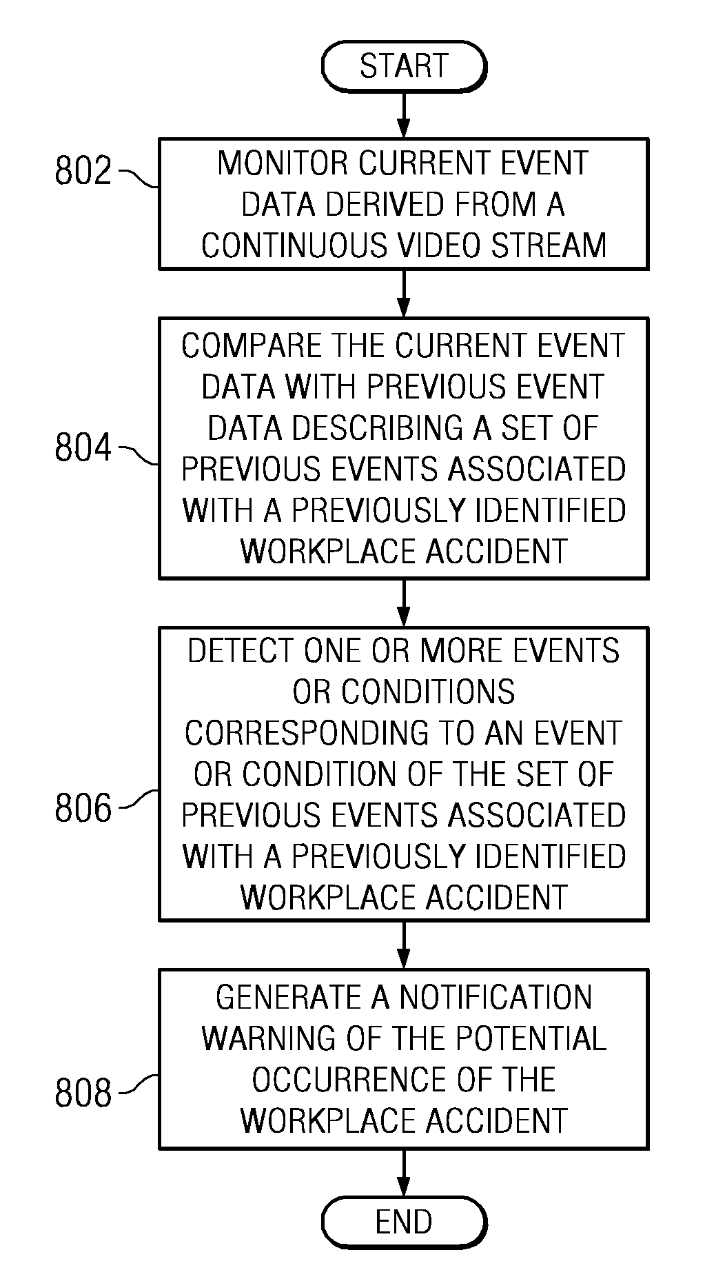
A computer implemented method, apparatus, and computer usable program product for predicting an occurrence of a workplace accident. The process monitors current event data derived from a continuous video stream. The current event data comprises metadata describing events occurring at a workplace. The process then compares the current event data with previous event data that describes a set of previous events associated with a previously identified workplace accident. In response to detecting events in the current event data corresponding to at least one event in the set of previous events, the process generates a notification identifying a potential occurrence of the workplace accident.

Description

CROSS-REFERENCE TO RELATED APPLICATIONS[0001]The present invention is related to the application entitled Intelligent Surveillance System and Method for Integrated Event Based Surveillance, application Ser. No. 11 / 455,251 (filed Jun. 16, 2006), assigned to a common assignee, and which is incorporated herein by reference.BACKGROUND OF THE INVENTION[0002]1. Field of the Invention[0003]The present invention relates generally to an improved data processing system, and in particular, to a computer implemented method and apparatus for processing video and audio data. Still more particularly, the present invention relates to a computer implemented method, apparatus, and computer usable program product for utilizing digital video technology to prevent workplace accidents by automatically identifying potentially unsafe work environments through analysis of event data derived from a continuous video stream.[0004]2. Description of the Related Art[0005]A workplace accident is an unintended even...

Claims


Application Information

Patent Timeline
IPC IPC(8): G06Q10/00
CPCG06Q10/0635G06Q10/00
Inventor ANGELL, ROBERT LEEKRAEMER, JAMES R.
Owner IBM CORP
Learn More