Eye Scanner with Integrated Focus Distance Determination Mechanism

Inactive Publication Date: 2009-04-09
CROSS MATCH TECH
View PDF2 Cites 11 Cited by
  • Summary
  • Abstract
  • Description
  • Claims
  • Application Information

AI Technical Summary

Benefits of technology

[0012]The present invention solves the above-mentioned needs by providing an eye scanner with an attached visor. One end of the visor is attached to the main body of the scanner. The other end of the visor is contoured in shape so that the forehead of a person tends to fit into the contour of the visor. A person may place their forehea

Problems solved by technology

However, such focusing mechanisms introduce substantial mechanical complexity, along with a requirement that a determination be made via some means or mechanism to ascertain when the desired physiologic features of the eye are actually in focus.
Such translational movement of optics further-from and closer-to the eye may also be cumbersome and undesirable for users.

Method used


Image

  • Eye Scanner with Integrated Focus Distance Determination Mechanism
  • Eye Scanner with Integrated Focus Distance Determination Mechanism
  • Eye Scanner with Integrated Focus Distance Determination Mechanism

Examples


Embodiment Construction

[0030]I. Overview

[0031]II. Exemplary Scanner

[0032]III. Exemplary Scanner With Visor

[0033]IV. Exemplary Usage

[0034]V. Exemplary Joints and Hinges

[0035]VI. Exemplary Visor Cap Hinge

[0036]VII. Further Embodiments

[0037]VIII. Conclusion

I. Overview

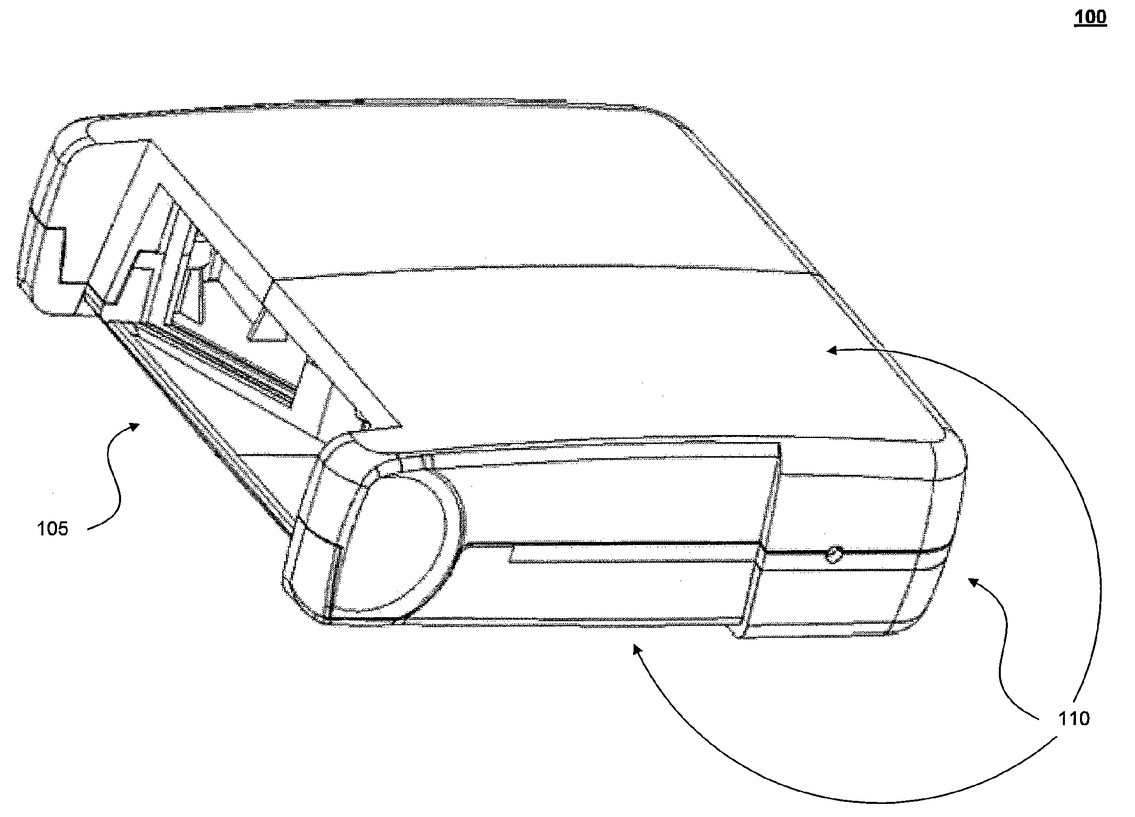
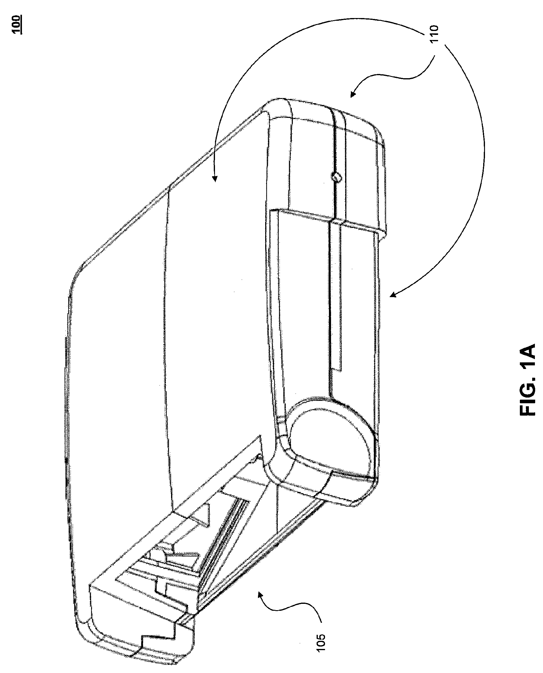
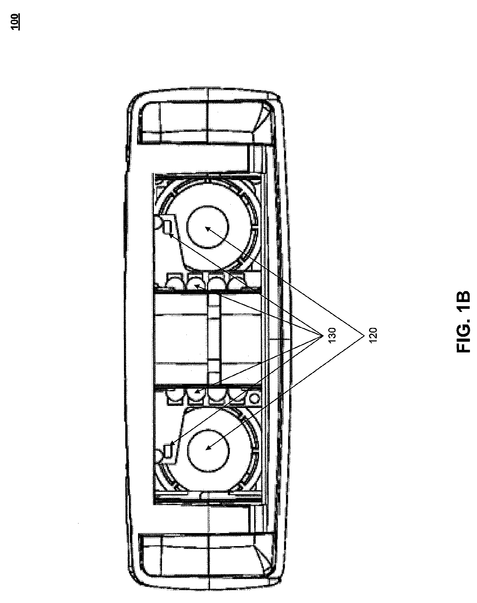
[0038]Embodiments of the present invention provide a scanner suitable for scanning the eye or eyes of a person. A suitable, approximately fixed relative position between the scanner optics and the person's eyes, as well as a suitable orientation between the scanner and the person's head, may be established by means of a rigid or substantially rigid visor which extends from the main body of the scanner. In particular, a suitable distance between the scanner optics and the person's eyes may be established by means of the rigid or substantially rigid visor which extends from the main body of the scanner. The suitable position, orientation, and / or distance of the person's eye or eyes and head in relation to the scanner optics ensures that at least a...


PUM


Abstract

A hand-held iris scanner, used for identifying individuals, has a visor mechanism connected to the main body of the scanner via a hinged attachment. The visor mechanism can be folded and locked into an extended position, wherein the free-floating end of the visor (that is, the non-hinged end) provides a contoured surface against which a user may place his or her forehead. By placing the forehead against the visor, the user automatically positions their eyes within a field of view of the scanner optics, and at a substantially optimum distance for correctly focused imaging by the scanner optical system. The visor mechanism may also be folded and locked into a second position wherein the bulk of the visor is substantially flush with the main body of the scanner, allowing for compact storage. An optional cap attachment on the visor provides a cover mechanism to protect the scanner optics when the scanner is not in use.

Description

BACKGROUND OF THE INVENTION[0001]1. Field of the Invention[0002]The present invention relates generally to the field of biometrics. The present invention relates more particularly to scanning devices used to identify persons or other living beings based on biometrics associated with the eye.[0003]2. Background Art[0004]Biometrics is a science involving the analysis of biological characteristics. Biometric imaging captures a measurable characteristic of a human being or other living organism, typically a mammal, for identity purposes. See, for example, Gary Roethenbaugh, Biometrics Explained, International Computer Security Association, Inc. (1998), pp. 1-34, which is incorporated herein by reference in its entirety.[0005]Eye scanners are biometric imaging systems for acquiring images of the human eye or the eye of other mammals for identity purposes. Two common types of eye scanners are iris scanners and retinal scanners, each of which rely on the distinctive patterns of the human i...

Claims


Application Information

Patent Timeline
IPC IPC(8): G06K9/00
CPCA61B5/117G06K9/00604G06K9/00335G06V40/20G06V40/19A61B5/1171
Inventor CARVER, JOHN F.MCCLURG, GEORGE WILLIAMWILL, ADAM MARKHODGES, DOUGLAS S.FEDELE, DEAN JOHN
Owner CROSS MATCH TECH
Why Eureka
Try Eureka