Joint design for welding plastic assemblies

Inactive Publication Date: 2011-08-25
GM GLOBAL TECH OPERATIONS LLC
View PDF2 Cites 4 Cited by
  • Summary
  • Abstract
  • Description
  • Claims
  • Application Information

AI Technical Summary

Benefits of technology

[0005]The present invention solves this need by providing an improved weldable component, weld joint, and method of welding. The weldable component includes a weld rivet attached by a thin portion, which is designed to break during the ultrasonic we

Problems solved by technology

When filled plastics, such as glass filled nylon and the like, are spot welded, the tool is subject to severe wear.
Consequently, the tool has to be made of extremely hard materials, which are often exotic and expensive, and it must be replaced frequently.
In addition, with spot welding no space or gap can be tolerated between the parts

Method used


Image

  • Joint design for welding plastic assemblies
  • Joint design for welding plastic assemblies
  • Joint design for welding plastic assemblies

Examples


Embodiment Construction

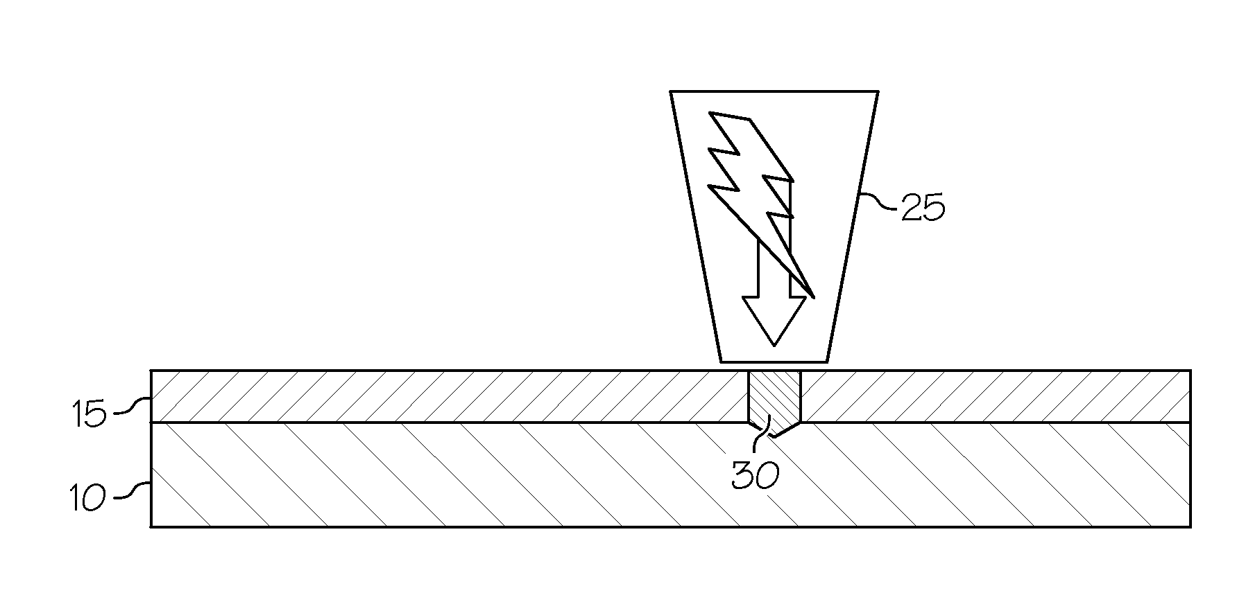
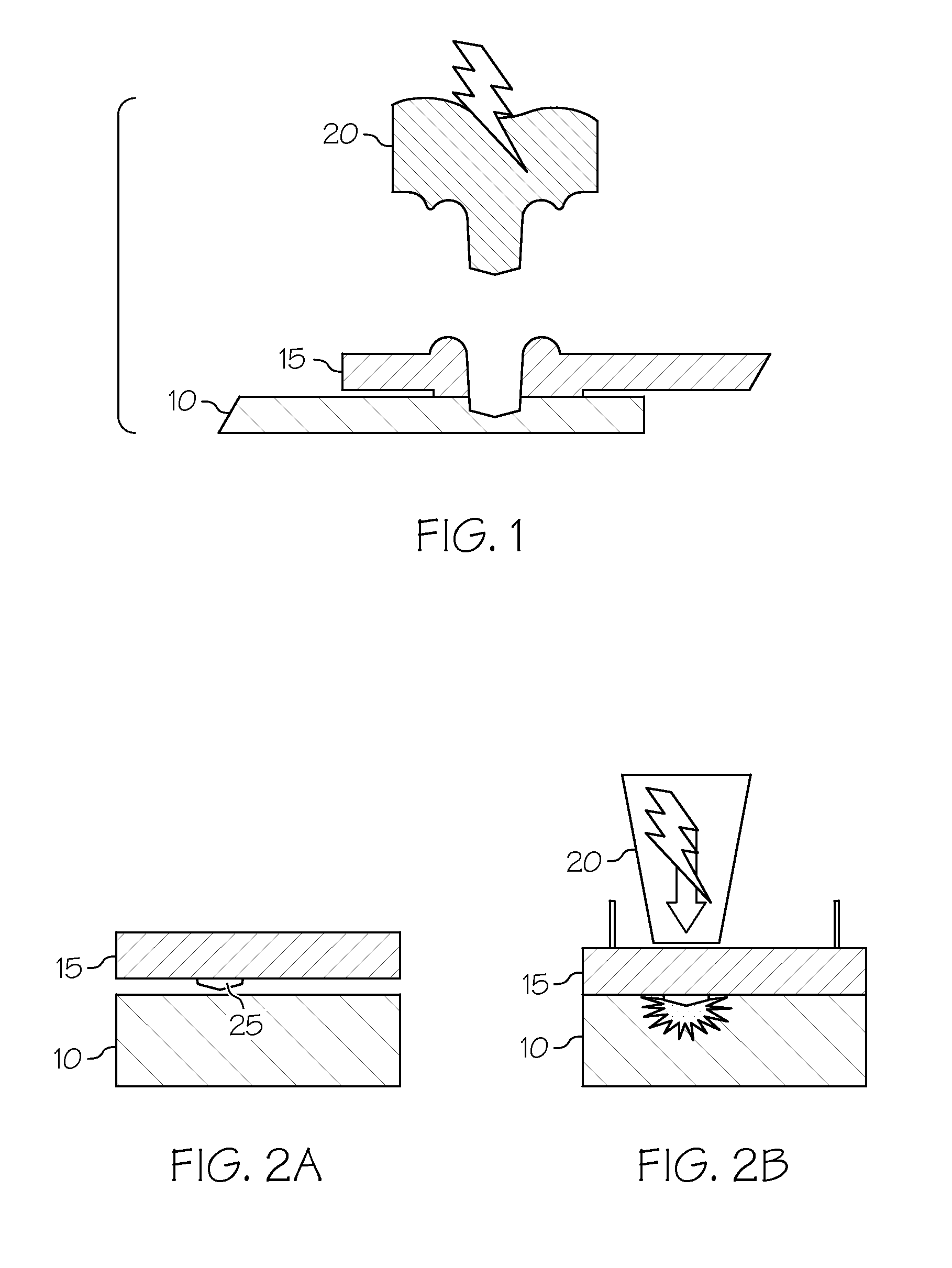
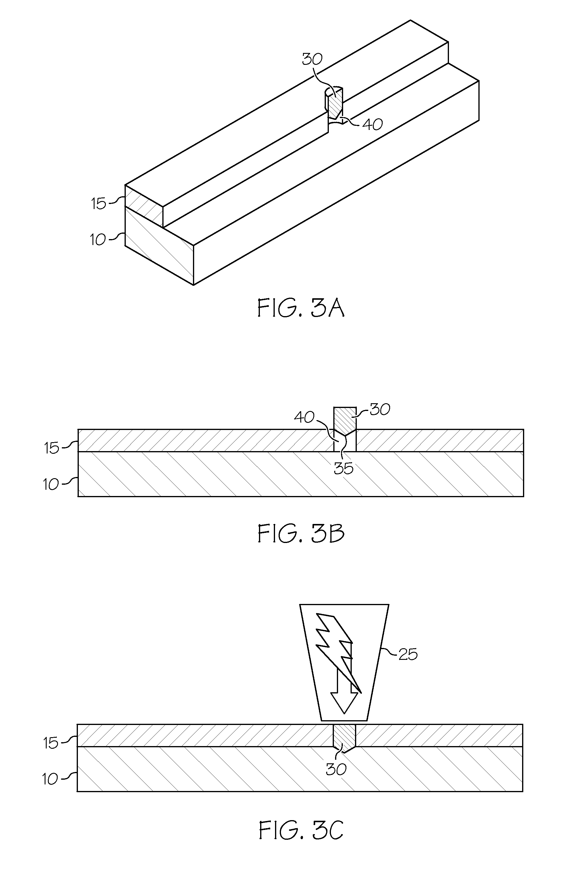
[0012]An improved weld joint and method of welding are provided. A weld rivet is molded in place as a part of the weldable component. This eliminates the use of an additional component in the welding process, which is undesirable. The weld rivet is joined to the main body of the weldable component by a thin area of plastic. It is designed to break free during the ultrasonic welding process, allowing it to move in line with the weld force and embed in the base component. This allows the assembled components to remain stationary and to be held in place accurately during the welding process. The weld tooling does not penetrate the assembly, which reduces the significant tool wear issues for filled materials. In addition, part fit-up is less critical than with a spot weld. It is possible to weld components even when there is a gap between them because the rivet is capable of moving until contact with the base component. Furthermore, the present welding process will leave less surface di...


PUM

PropertyMeasurementUnit
Angleaaaaaaaaaa
Angleaaaaaaaaaa
Shapeaaaaaaaaaa

Abstract

A weldable component is described. The weldable component includes a weld rivet attached by a thin portion, which is designed to break during the ultrasonic welding process. The weld rivet is driven through a complementary void pocket which extends through the part and is positioned under the weld rivet. The weld rivet is embedded in the base component to form the weld. A welded joint and a method for ultrasonic welding using the weldable component are also described.

Description

BACKGROUND OF THE INVENTION[0001]This invention relates generally to ultrasonic welding, and more particularly to a joint design and a method for welding plastic assemblies.[0002]Various methods for welding plastic parts are known. Current ultrasonic welding techniques include spot welding and energy director welding. In a spot welding joint, the parts are stationary during the welding process. As shown in FIG. 1, the weldable component 15 is placed on the base component 10. The ultrasonic welding tool 20 penetrates the weldable component 15 and the base component 10 in order to form the spot weld joint. When filled plastics, such as glass filled nylon and the like, are spot welded, the tool is subject to severe wear. Consequently, the tool has to be made of extremely hard materials, which are often exotic and expensive, and it must be replaced frequently. In addition, with spot welding no space or gap can be tolerated between the parts to be joined. Also, the cosmetic appearance of...

Claims


Application Information

Patent Timeline
IPC IPC(8): B32B3/10B29C65/08
CPCB29C65/08Y10T156/109B29C65/608B29C65/609B29C66/1122B29C66/21B29C66/3022B29C66/30221B29C66/43B29C66/45B29C66/71B29C66/7212B29C66/8322B29C65/564Y10T428/24273B29C66/81429B29C66/81423B29C66/81417B29K2077/00B29K2309/08B29C66/81264B29C66/7392
Inventor HAYSLIP, JASON M.
Owner GM GLOBAL TECH OPERATIONS LLC
Why Eureka
Try Eureka