Assembling Block

a technology of assembling blocks and blocks, applied in the direction of mechanical devices, toys, fastening means, etc., can solve the problems of limited shape variation of constructed joints, add to manufacturing costs, etc., and achieve the effect of low cost, easy disassembly, and easy pulling ou

Active Publication Date: 2009-04-09
YOSHIRITSU
View PDF14 Cites 9 Cited by
  • Summary
  • Abstract
  • Description
  • Claims
  • Application Information

AI Technical Summary

Benefits of technology

[0017]Using this assembling block, it is possible to form surfaces that form any desired angle relative to each other by bending the joint at any desired angle. By inserting a plurality of such joints between any two seat portions and any one retaining piece of the block plate, and bending the individual joints at different angles from each other, block plates can be coupled to the respective joints so as to extend in a plurality of different directions from each other.
[0018]It is therefore possible to assemble various three-dimensional objects without preparing many kinds of joints. No strict dimensional control is necessary either. Thus, such three-dimensional objects can be manufactured at a low cost.
[0019]The assembling blocks according to the present invention can be used not only as toys, but to assemble other practical articles such as handicrafts, decorations, and shades for lighting devices. Also, using large and high-strength block plates and joints, it is possible to assemble a large structure such as a building or a vehicle.
[0020]The joint can be easily pulled out from between the seat portions and the retaining piece by deflecting and disengaging the joint from the seat portions or the retaining piece. A three-dimensional object assembled from the assembling blocks according to the present invention can thus be easily disassembled.

Problems solved by technology

In this assembling block, because the coupling angle between the block plates and the number of block plates that can be coupled together are limited according to the type of the joint used, variation in shape of constructed joints is limited even if many different kinds of joints are prepared.
Thus, strict dimensional control is required for the end product, which adds to the manufacturing cost.

Method used


Image

  • Assembling Block
  • Assembling Block
  • Assembling Block

Examples


first embodiment

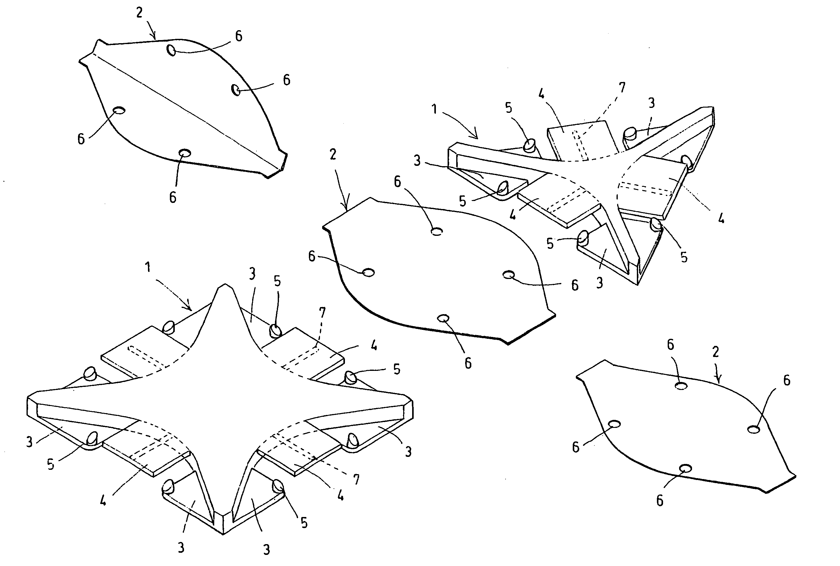
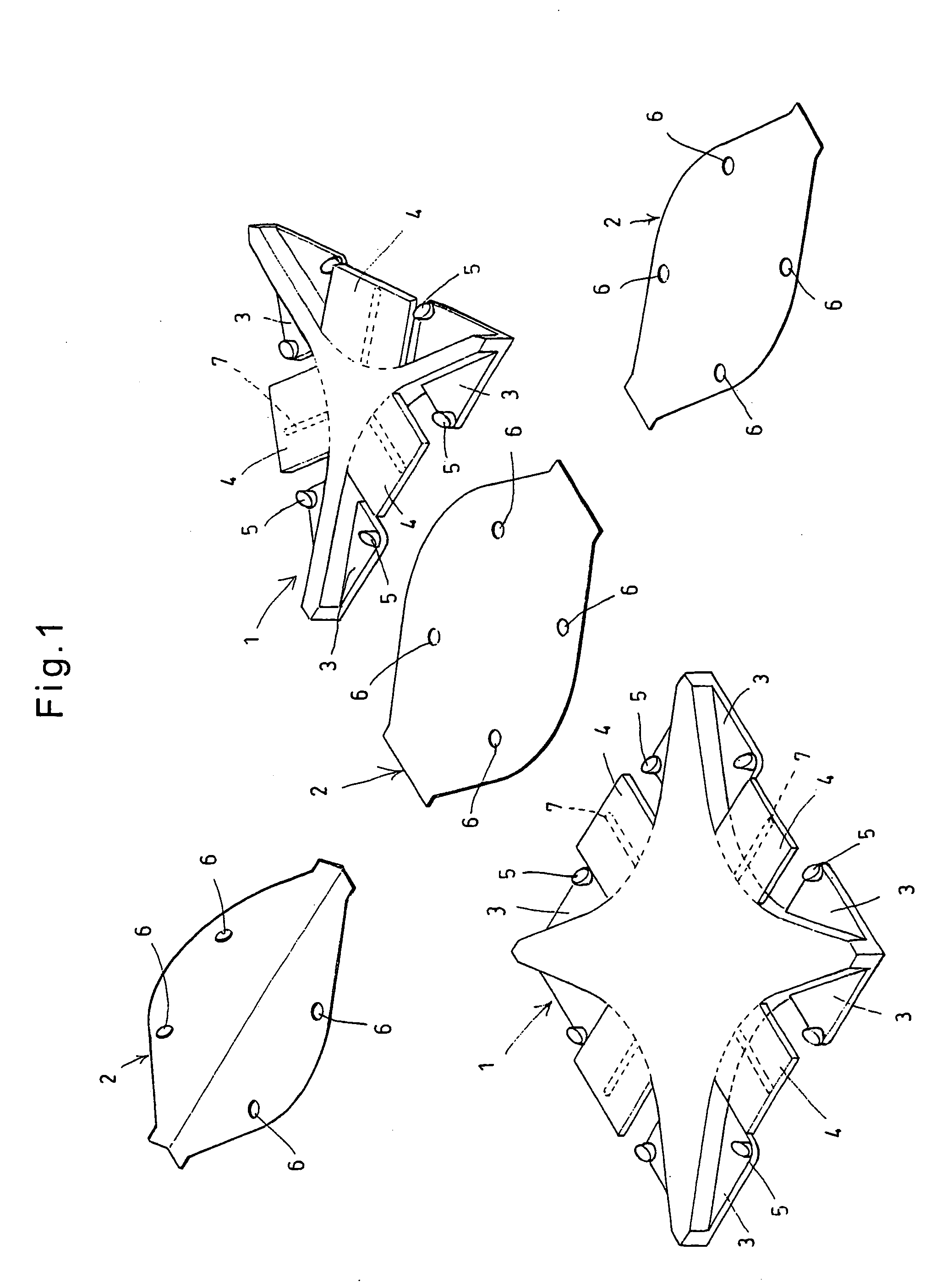
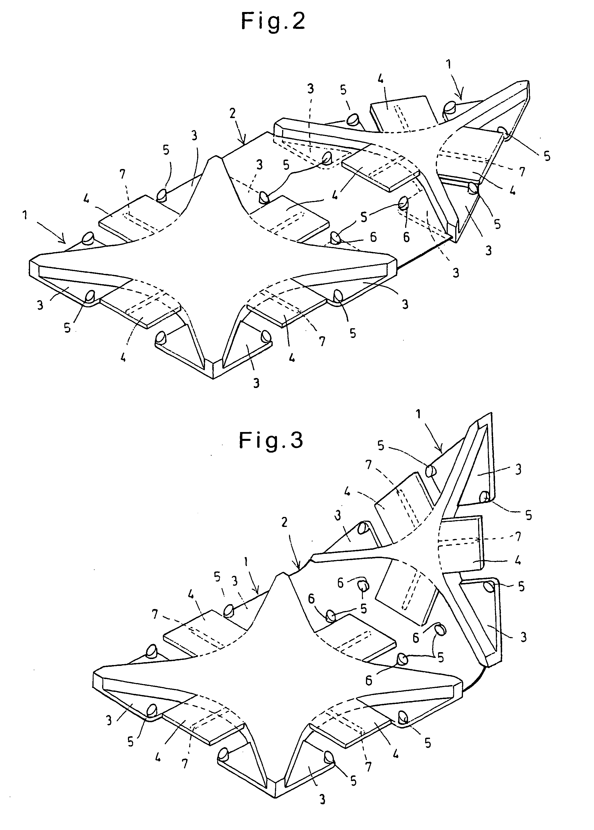
[0063]this invention is now described with reference to FIGS. 1 to 4.

[0064]As shown in FIG. 1, this assembling block comprises block plates 1 which are in the shape of an equilateral triangle and a square, respectively, as viewed from top, and joints 2 through which the block plates 1 are coupled together. The block plates 1 are hard members formed by molding a plastic material such as acrylic resin in a mold. The block plates 1 have sides that are equal in length to each other and thicknesses that are also equal to each other.

[0065]Each block plate 1 includes seat portions 3 provided along the respective sides of the block plate, and retaining pieces 4 extending from the center of the block plate to the outer edge thereof and spaced from the seat portions 3 in the thickness direction. The seat portions 3 are provided at both ends of the respective sides so as to be spaced from each other. Each seat portion 3 has a step in its inner portion and is formed with an engaging protrusion ...

third embodiment

[0080]In the third embodiment shown in FIG. 10, engaging protrusions 5 are formed on the joint by bulging e.g. by pressing, and engaging holes 6 are formed in the block plate 1. In this case, the engaging holes 6 are formed in the retaining pieces 4 or the seat portions 3 according to the positions of the engaging protrusions 5.

[0081]In the first to third embodiments, the elements of the assembling block are made of a plastic material. But if the assembling blocks according to the present invention are used to manufacture a large structure for which strength and durability are required, such as a building or a vehicle, they may be formed of metal plates such as stainless steel plates, as in the fourth embodiment shown in FIG. 11.

[0082]The block plates 1 of this embodiment are each formed by pressing a metal plate formed with cuts to raise the retaining pieces 4 from the seat portions 3, and by bulging the seat portions 3 to form the engaging protrusions 5. Further, stoppers 9 are fo...

fifth embodiment

[0084]FIG. 13 shows a fifth embodiment, which is also an assembling block made of a metal. In this embodiment, an engaging protrusion 5 is formed on the back of each retaining piece 4, and a pocket 11 is formed on the corner of each seat portion 3. Pressing protrusions 3a and 11a are formed on the surface of each seat portions 3 and on the back of the pocket 11, respectively. The joint 2 has, on each side thereof, a pair of shoulders 2a and a pair of constricted portions 2b.

[0085]In this assembling block, as shown in FIG. 14, when the joint 2 is inserted between the seat portions 3 and the retaining piece 4, the engaging protrusion 5 engages in the corresponding engaging hole 6, and simultaneously, the shoulders 2a of the joint 2 are inserted into the respective pockets 11 of the block plate 1, thereby preventing turning up of the joint 2. Also simultaneously, the constricted portions 2b engage the ends of the respective pockets 11, and the pressing protrusions 3a and 11a sandwich ...


PUM

PropertyMeasurementUnit
angleaaaaaaaaaa
thicknessaaaaaaaaaa
distancesaaaaaaaaaa

Abstract

An assembling block is provided which includes block plates 1 having square and equilateral triangular plan shapes, respectively, and a joint 2 for connecting the block plates 1 together, wherein each of the block plates 1 includes seat portions 3 provided along the respective sides of the block plate, and retaining pieces 4 extending from the center of the block plate to the outer edge thereof and spaced from the seat portions 3 in the thickness direction, and wherein the joint comprises a plate member made of a flexible and bendable material, whereby when the joint 2 is inserted between two of the seat portions 3 and one of the retaining pieces 4 of each block plate 1, the joint 2 engages the seat portions 3 with engaging protrusions 5 formed on the seat portions 3 fitted in engaging holes 6 formed in the joint 2, thereby coupling the block plates 1 together. With this arrangement, it is possible to easily construct a large variety of objects using minimum kinds of joints. Such an assembling block can be manufactured at a low cost too.

Description

TECHNICAL FIELD[0001]This invention relates to an assembling block which can be coupled to other such blocks one after another to construct a three-dimensional object.BACKGROUND ART[0002]The present applicant proposed, based on the invention disclosed in the below-identified Patent document 1, an assembling block comprising block plates having square and equilateral triangular plan shapes, and a joint for coupling the block plates together.[0003]The block plates and the joint of this assembling block are formed by molding a hard plastic material. An insertion opening is formed along each side of the block plates. The joint has plugs extending in at least two directions and adapted to be received in the insertion openings.[0004]Different types of joints are prepared which are coupled to block plates in different ways. These joints include one having plugs that are flush with each other and extend in two directions, one having plugs extending in two directions that intersect each othe...

Claims


Application Information

Patent Timeline
Patent Type & Authority Applications(United States)
IPC IPC(8): B32B3/10
CPCA63H33/108A63H33/08A63H33/10
Inventor KICHIJO, HIROSHIKICHIJO, YOSHIIE
Owner YOSHIRITSU
Why Eureka
Try Eureka