
Onboard air conditioning system

a technology of air conditioning system and air outlet, which is applied in the direction of dashboard lighting device, vehicle heating/cooling device, transportation and packaging, etc., can solve the problems of not being comfortable for the vehicle occupant, unable to recognize the actual temperature of the conditioned air that is expelled, and conditioned air being expelled from each air outl

Inactive Publication Date: 2009-04-09
HONDA MOTOR CO LTD
View PDF22 Cites 28 Cited by
  • Summary
  • Abstract
  • Description
  • Claims
  • Application Information

AI Technical Summary

Benefits of technology

[0005]In view of such problems of the prior art, a primary object of the present invention is to provide an onboard air conditioning system that allows the user to readily sense the temperature of the conditioned air flowing out of an air outlet.
[0006]A second object of the present invention is to provide an onboard air conditioning system that allows the user to visually sense the temperature of the conditioned air flowing out of an air outlet.
[0007]A third object of the present invention is to provide an onboard air conditioning system that can introduce conditioned air into a cabin in a mild and comfortable manner.

Problems solved by technology

In such an automatic air conditioning system, the selected temperature is only numerically indicated on the control board, and the user is unable to recognize the actual temperature of the conditioned air that is expelled from air outlets which are provided in interior members such as a center console and an instrument panel unless the use places his or her hand or face close to the air outlet.
Another problem associated with the conventional air conditioning system is that the conditioned air is expelled from each air outlet as an air flow having a significant directivity.
When the conditioned air directly flows onto or impinges upon a part of the face, arm or other part of the vehicle occupant, it may not be comfortable to the vehicle occupant.

Method used


Image

  • Onboard air conditioning system
  • Onboard air conditioning system
  • Onboard air conditioning system

Examples


Embodiment Construction

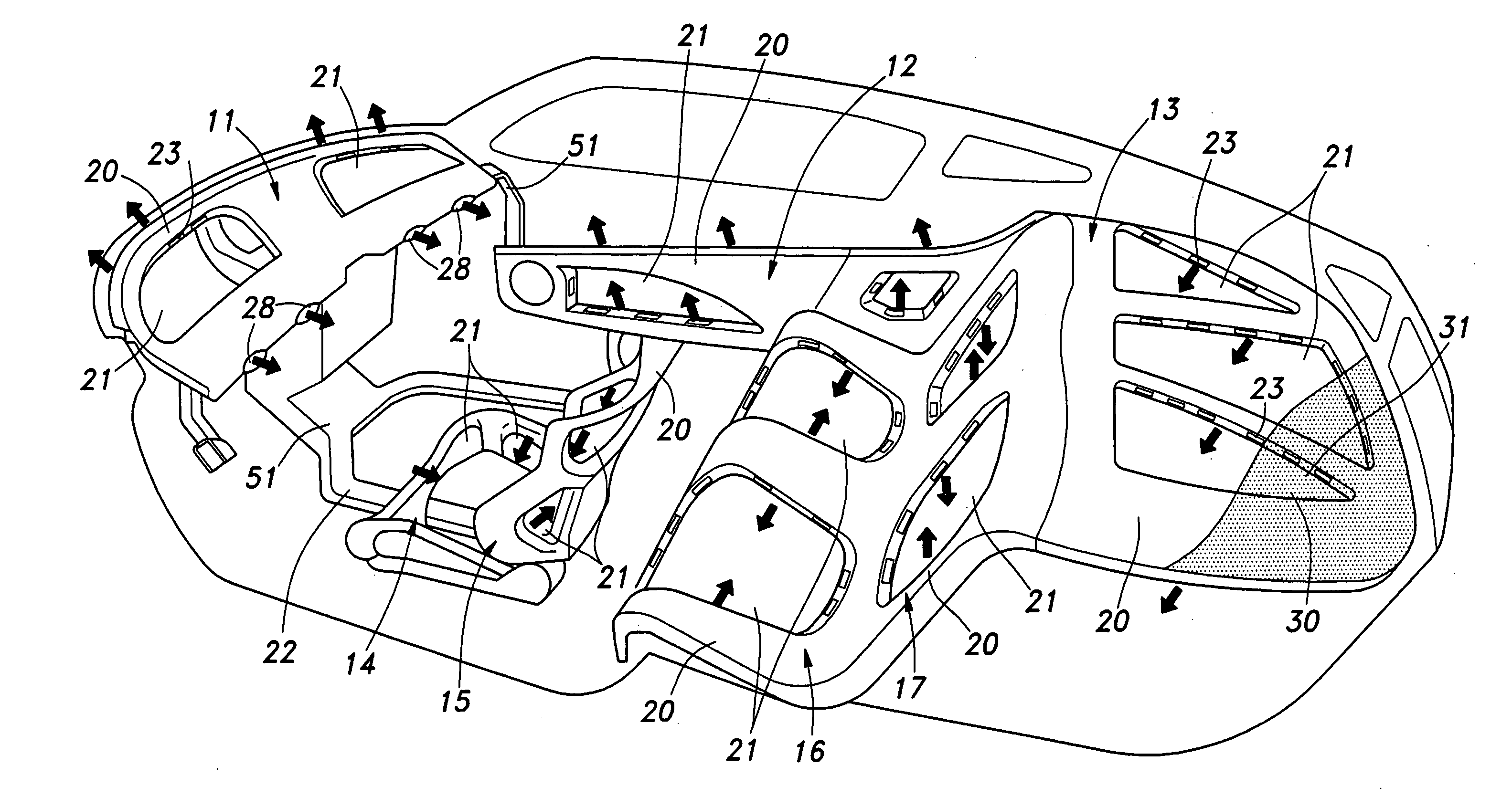
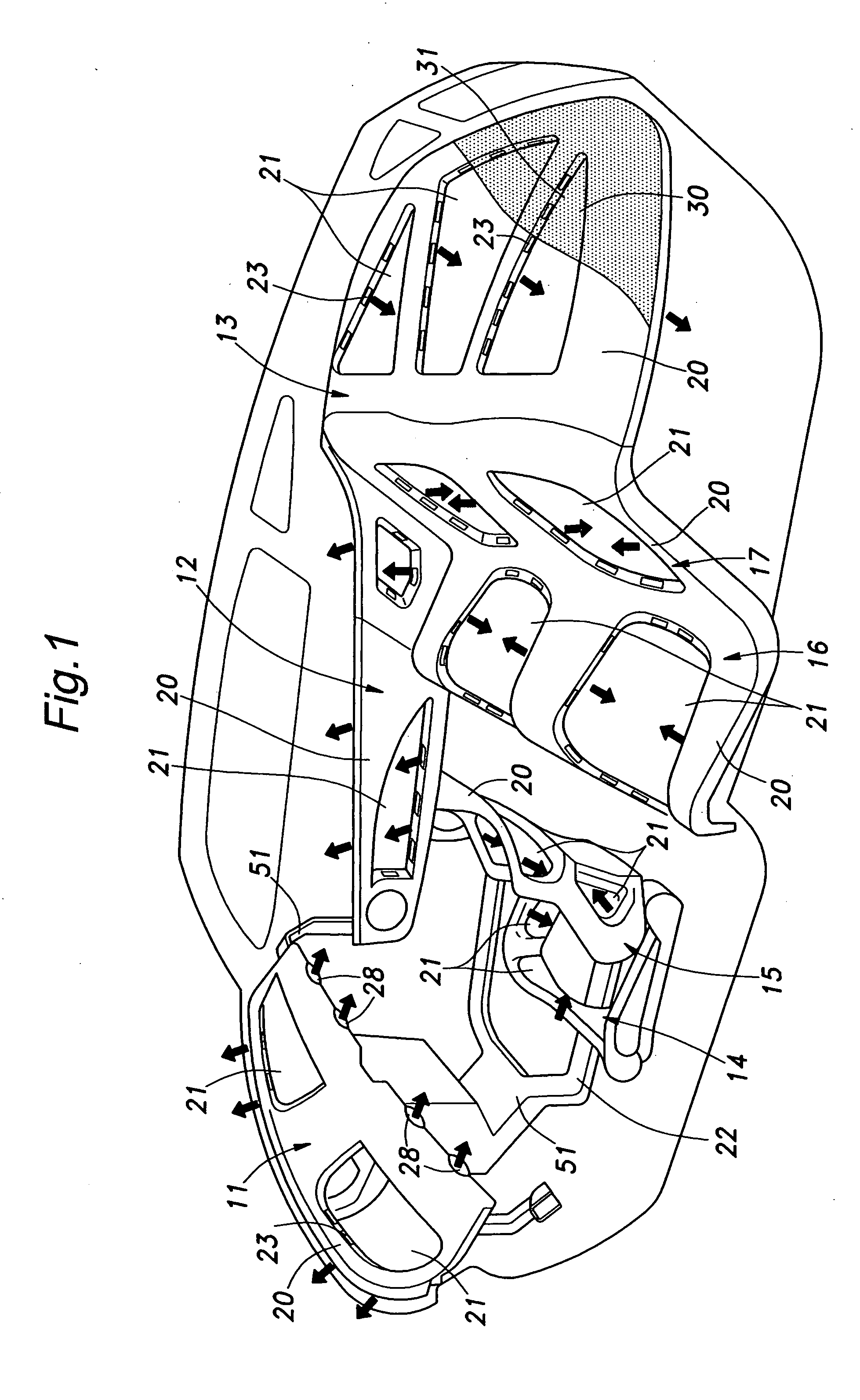
[0022]FIGS. 1 to 5 shows an onboard air conditioning system for a motor vehicle embodying the present invention. Referring to FIG. 1, this air conditioning system comprises air outlets 31 formed in various interior members such as an instrument panel 11, door garnishes 12, a rear shelf 13, front seat bottoms 14, front seat backs 15, rear seat bottoms 16 and rear seat backs 17.

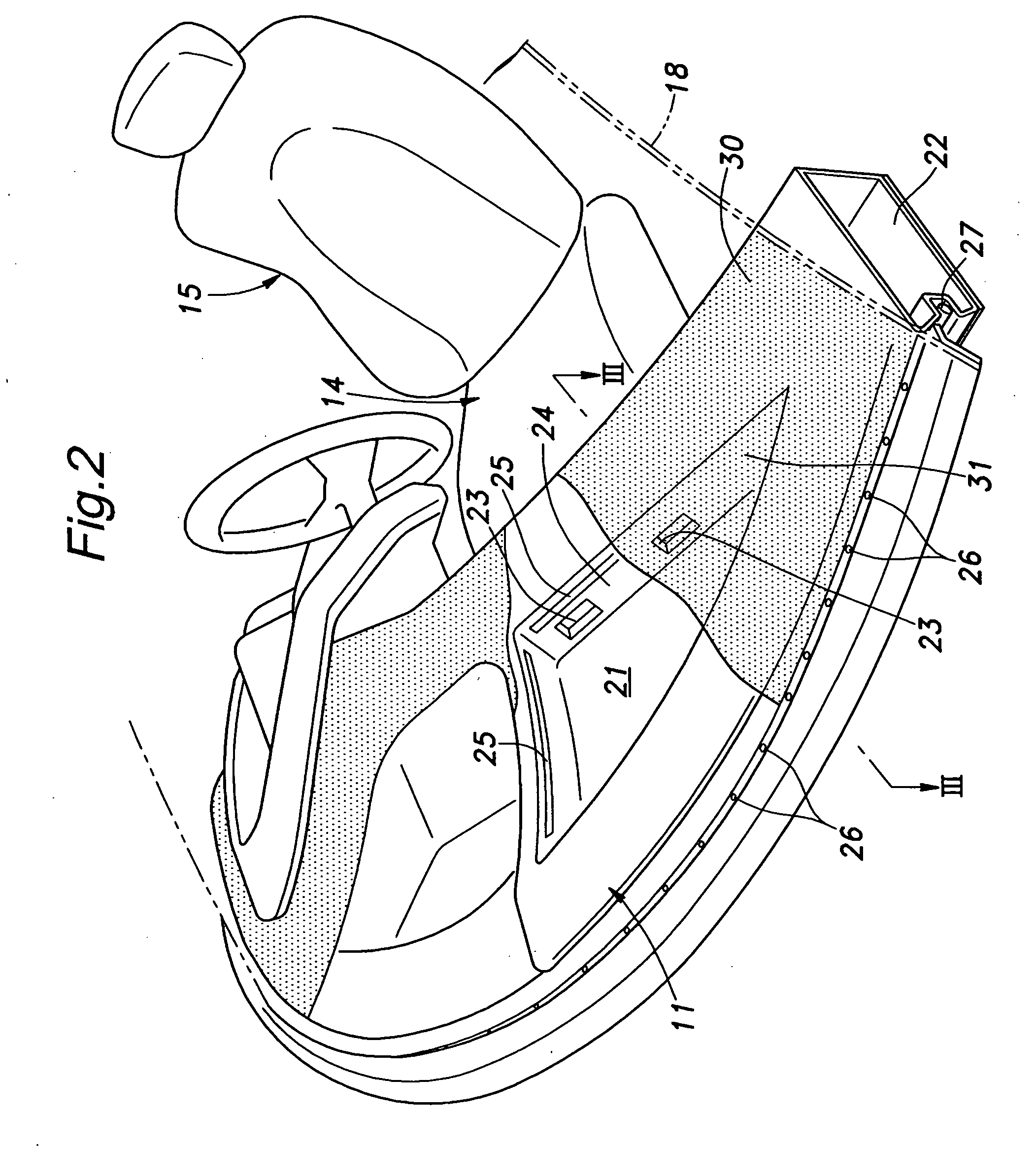
[0023]Each air outlet 31 is defined by an annular duct 20 which in turn defines a central chamber 21 which has a closed bottom and an open top that defines the corresponding air outlet 31. The annular duct 20 may entirely surround the air outlet 31 as shown in the illustrated embodiment, but may also only partly surround the air outlet 31. The annular duct 20 communicates with a corresponding main duct 22, and is provided with a plurality of communication holes 23 so as to face the central chamber 21. The air outlet 31 is covered by an air permeable sheet 30 typically made of woven or knit fabric or perforated ...


PUM


Abstract

In an onboard air conditioning system, a light source (25) for conditioned air is provided in association with an air outlet (31), and the color of the light emitted from the light source changes in dependence on the temperature of the conditioned air. The light source may consist of a linear light source at least partly surrounding the air outlet. Thereby, the vehicle occupant can visually recognize the operating condition of the air conditioning system. The air outlet may be at least partly-surrounded by an annular duct (20) defining a central chamber (21) that has a closed bottom and an open top defining the air outlet, the annular air duct being provided with a communication hole (23) communicating an interior of the annular duct with the central chamber, and the air outlet is covered by an air permeable sheet (30). The conditioned air is thus turned into a mild one because the central chamber is typically large in size, and the velocity of the expelled air may be extremely small for a given volume of conditioned air.

Description

TECHNICAL FIELD[0001]The present invention relates to an onboard air conditioning system typically for use in a motor vehicle, and in particular to an onboard air conditioning system that can visually indicate the temperature of the conditioned air.BACKGROUND OF THE INVENTION[0002]An onboard air conditioning system for a motor vehicle is typically provided with a control board on an instrument panel or a center console so that a vehicle operator or a passenger may be able to manually operate the air conditioning system. In the case of a manually controlled air conditioning system, the control board typically includes a temperature selector for selecting a desired temperature of the controlled air and an air flow selector. In the case of an automatic air conditioning system, the control board includes a temperature setting switch that enables the user to set a desired temperature for a thermostat control, and the set temperature is indicated on a small LCD panel included in the contr...

Claims


Application Information

Patent Timeline
IPC IPC(8): B60H1/00
CPCB60H1/247B60Q3/0243B60Q2500/20B60Q3/048B60Q9/00B60Q3/0293B60Q3/20B60Q3/80B60Q3/18
Inventor OKITA, TAKUYANAKAGAWA, TORUTSUCHIYA, SATORU
Owner HONDA MOTOR CO LTD
Learn More