
Brace for Reducing a Metacarpal Fracture

a technology for metacarpal fractures and braces, applied in the field of braces for reducing metacarpal fractures, can solve the problems of difficult correction, fracture reduction, and metacarpal fractures, and achieve the effect of reducing fractures

Inactive Publication Date: 2009-04-09
MACARTHUR ROBERT
View PDF8 Cites 5 Cited by
  • Summary
  • Abstract
  • Description
  • Claims
  • Application Information

AI Technical Summary

Benefits of technology

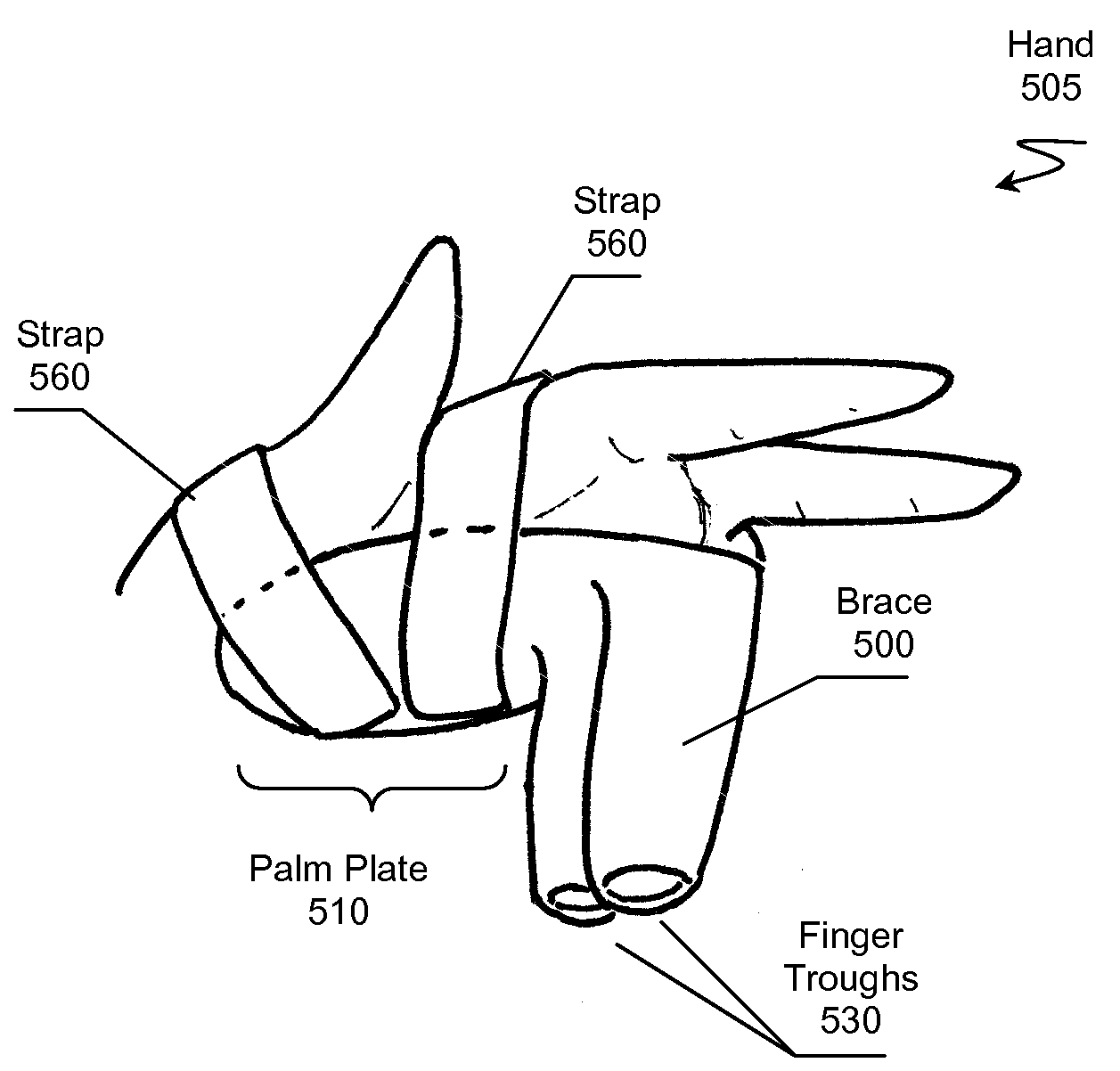
[0007]The present invention provides apparatus, systems and methods in which a metacarpal fracture (e.g., a boxer's fracture) can be secured using a brace to reduce the fracture. The brace includes a palm plate and a finger trough coupled to the palm plate at a proper angle of flexion. The brace can also include a support tube that can be placed around the finger having the fracture. The tube and finger can be inserted into the trough. An adjuster coupled to the trough can position the tube by moving the tube axially toward the head of the fractured metacarpal causing the finger to apply appropriate axial compression to the fractured metacarpal, restoring it to a proper position. The brace also preferably includes a fastener system that holds the palm plate and trough in a stable position on an individual's hand. In a preferred embodiment, the palm plate, trough, and support tube are substantially radiolucent.

Problems solved by technology

Metacarpal fractures, a boxer's fracture for example, are difficult to correct because the metacarpal-phalangeal (MP) joint should be immobilized at a proper flexion angle (e.g., about 90 degrees) to promote proper healing.
These and other braces fail to achieve proper fracture reduction due to the hypothenar pad and required pressure on the palmar side of the MP joint, thereby immobilizing the MP joint in extension.
Keeping the MP joint in extension can cause permanent extension contracture.
Although the above braces have found their respective niches in the market, they collectively fail to offer the standard reduction maneuver for a metacarpal fracture over an extended period of time and, among other issues, fail to allow for mobility of remaining fingers.

Method used


Image

  • Brace for Reducing a Metacarpal Fracture
  • Brace for Reducing a Metacarpal Fracture
  • Brace for Reducing a Metacarpal Fracture

Examples


Embodiment Construction

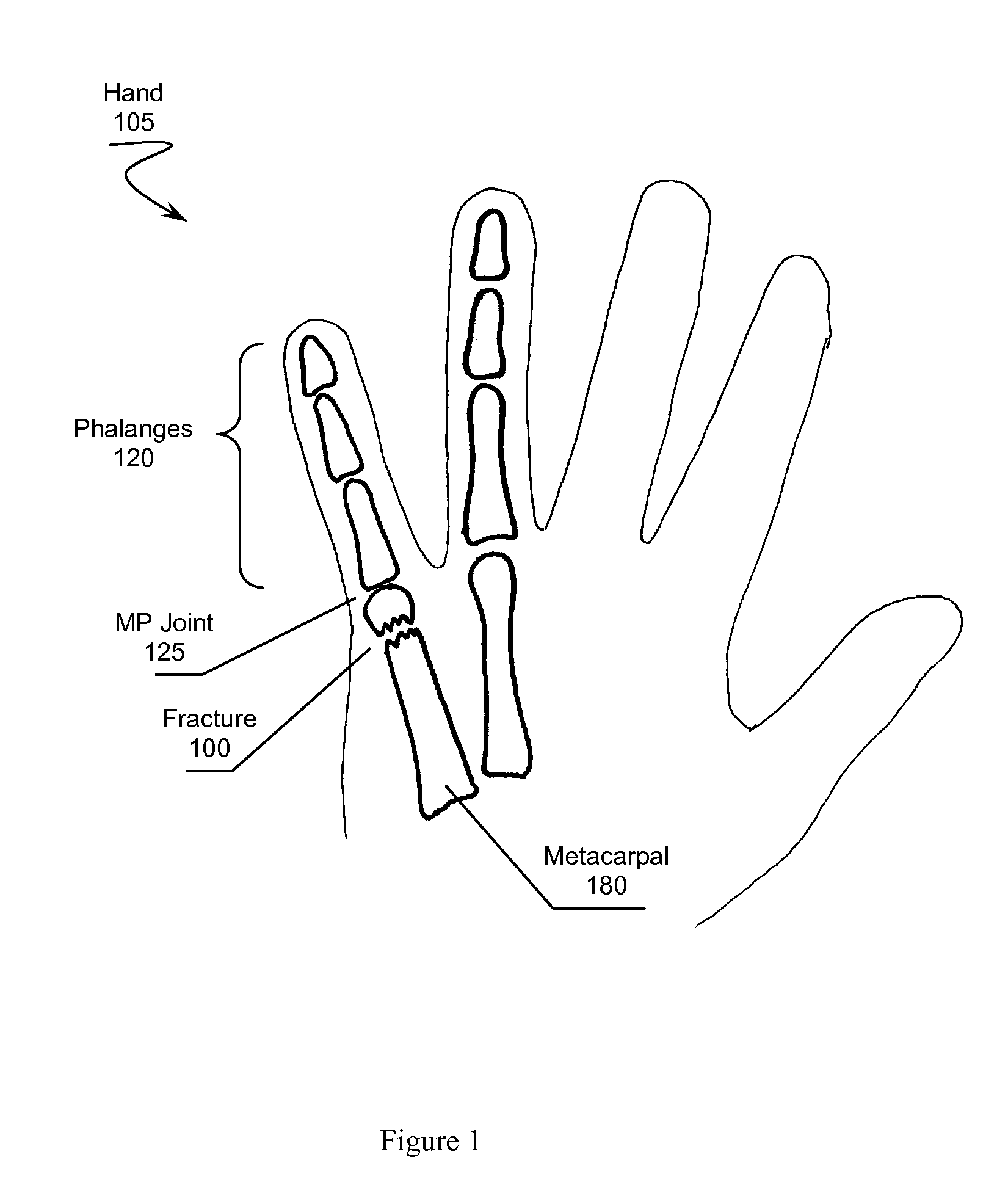
[0016]In FIG. 1, hand 105 has experienced a metacarpal fracture 100, for example a boxer's fracture. Fracture 100 can be reduced by the use of a brace that induces a proper angle of flexion (e.g., about a 90 degree flexion angle) at MP joint 125 located between phalanges 120 and metacarpal 180. The brace can also be constructed to apply an axial pressure along phalanges 120 to reduce the apex of fracture 100.

Brace Overview

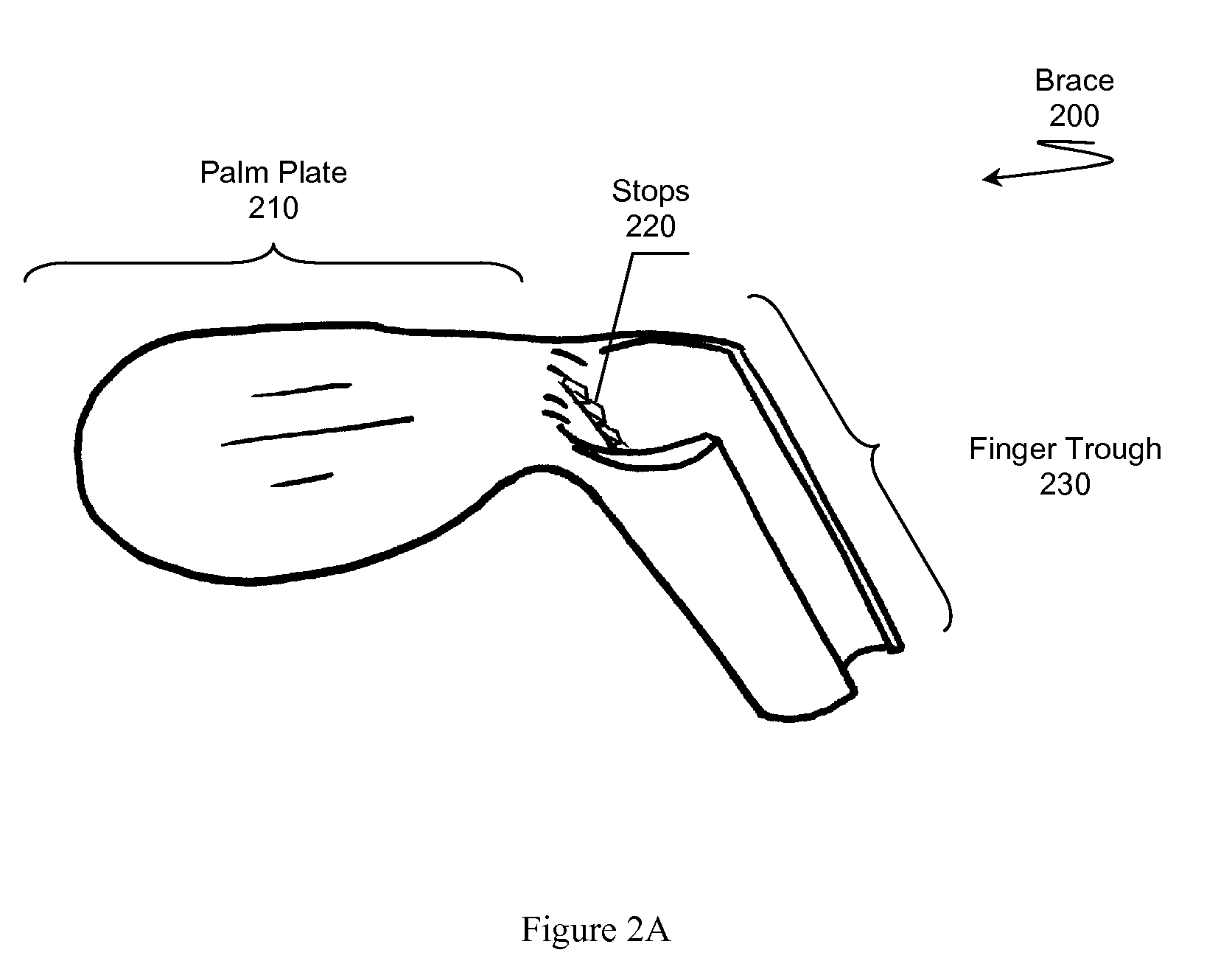
[0017]In FIG. 2A, brace 200 comprises palm plate 210 and finger trough 230 that provide for proper reduction of a metacarpal fracture. Palm plate 210 preferably is placed on the palmar side of a hand having a metacarpal fracture. The finger associated with the metacarpal fracture is inserted into trough 230. Finger trough 230 and plate 210 cause the finger to reside at a proper angle of flexion.

[0018]Palm plate 210 approximately defines a plane that is roughly parallel to the metacarpals of the hand having the fracture. The angle of flexion provided by finger troug...


PUM


Abstract

A brace for reducing a metacarpal fracture is presented. The brace comprises a palm plate and a finger trough for receiving a finger having a metacarpal fracture. The trough couples to the palm plate at a proper angle of flexion for reducing the fracture. An individual places the brace on the plamar side of their hand and places the finger having the fracture in the trough. A fastening system holds the brace in a stable position on the hand. The trough maintains the metacarpal-phalangeal joint at the proper angle of flexion while also maintaining necessary axial compression along the finger to reduce the fracture.

Description

[0001]This application claims the benefit of priority to U.S. provisional application having Ser. No. 60 / 998,311 filed on Oct. 7, 2007. This and all other extrinsic materials discussed herein are incorporated by reference in their entirety. Where a definition or use of a term in an incorporated reference is inconsistent or contrary to the definition of that term provided herein, the definition of that term provided herein applies and the definition of that term in the reference does not apply.FIELD OF THE INVENTION[0002]The field of the invention is fracture reduction technologies.BACKGROUND[0003]Metacarpal fractures, a boxer's fracture for example, are difficult to correct because the metacarpal-phalangeal (MP) joint should be immobilized at a proper flexion angle (e.g., about 90 degrees) to promote proper healing. The standard reduction technique for a boxer's fracture includes flexing the little finger's MP joint to 90 degrees and pushing axially along the finger to place the fra...

Claims


Application Information

Patent Timeline
IPC IPC(8): A61F5/00
CPCA61F5/05875
Inventor MACARTHUR, ROBERT
Owner MACARTHUR ROBERT
Learn More