
Manufacturing method of pneumatic tire, and pneumatic tire

a manufacturing method and tire technology, applied in the field of pneumatic tire manufacturing method and pneumatic tire, can solve the problems of uneven tire uniformity and hindering comfortable riding, and achieve the effect of reducing manufacturing axe obstacles and improving run-flat durability

Inactive Publication Date: 2009-04-16
BRIDGESTONE CORP
View PDF8 Cites 2 Cited by
  • Summary
  • Abstract
  • Description
  • Claims
  • Application Information

AI Technical Summary

Benefits of technology

[0013]In this invention, the reinforcing rubber which constitutes the reinforcing rubber layer in the pneumatic tire is formed by winding a plurality of beltlike reinforcing rubber sheets onto the forming drum. Accordingly, as well as the thickness of each reinforcing rubber sheet which constitutes this reinforcing rubber can be made smaller than the thickness of a conventional reinforcing rubber, the thickness of the overlapping portion can be made larger than the thickness of the conventional reinforcing rubber, As a result, run-flat durability can be improved, without hindering comfortable riding.
[0014]Moreover, since the plurality reinforcing rubber sheets which constitute the reinforcing rubber have almost the same cross-sectional area and cross-sectional shape, it is possible to mold these reinforcing rubber sheets under the same extruding conditions, using the same mouthpiece. As a result, an increase in manufacturing cost can be suppressed.
[0025]According to the invention, the pneumatic tire with improved run-flat durability without hindering comfortable riding can be formed while hindrances to manufacture axe minimized.
[0023]Furthers the pneumatic tire of the invention is formed by the above manufacturing method of a pneumatic tire.
[0024]Here, the shore A hardness of the reinforcing rubber layer may be 70° or more and 85° or less.
[0025]According to the invention, the pneumatic tire with improved run-flat durability without hindering comfortable riding can be formed while hindrances to manufacture axe minimized.

Problems solved by technology

However, in this case, as the thickness of the reinforcing rubber layer becomes large in the pneumatic tire, variations in this thickness become large, As a result, uniformity of the tire may get worse, and comfortable riding may be hindered,

Method used


Image

  • Manufacturing method of pneumatic tire, and pneumatic tire
  • Manufacturing method of pneumatic tire, and pneumatic tire
  • Manufacturing method of pneumatic tire, and pneumatic tire

Examples


Embodiment Construction

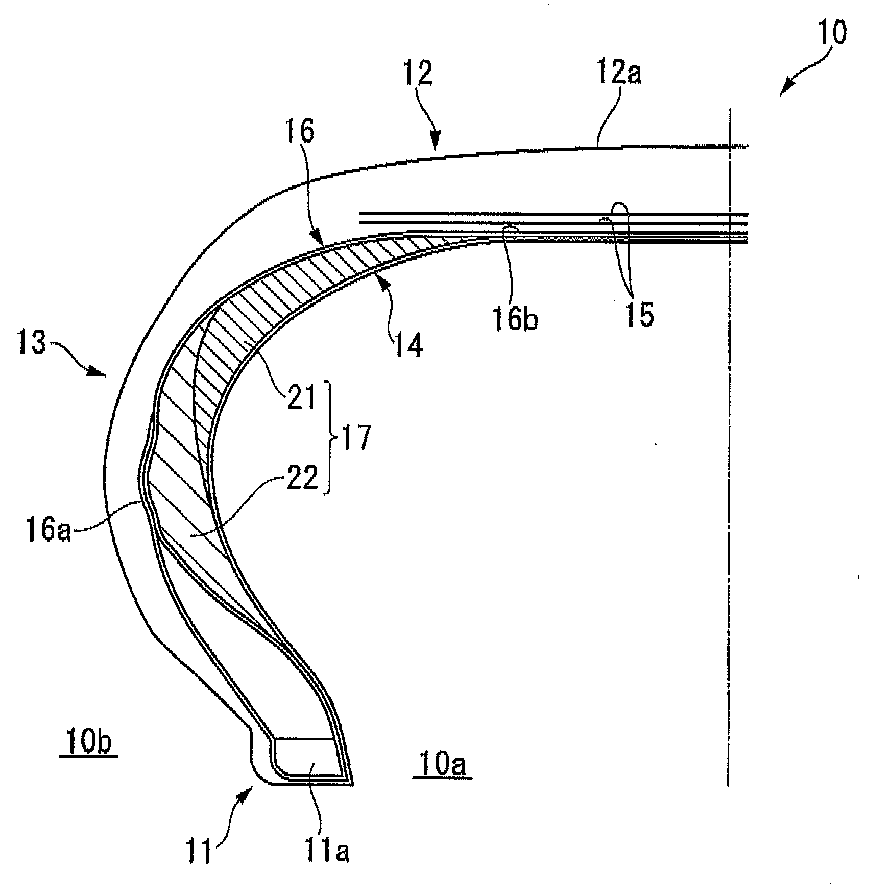
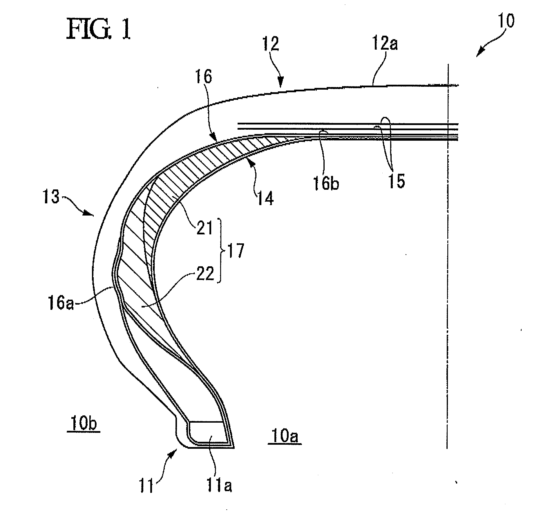
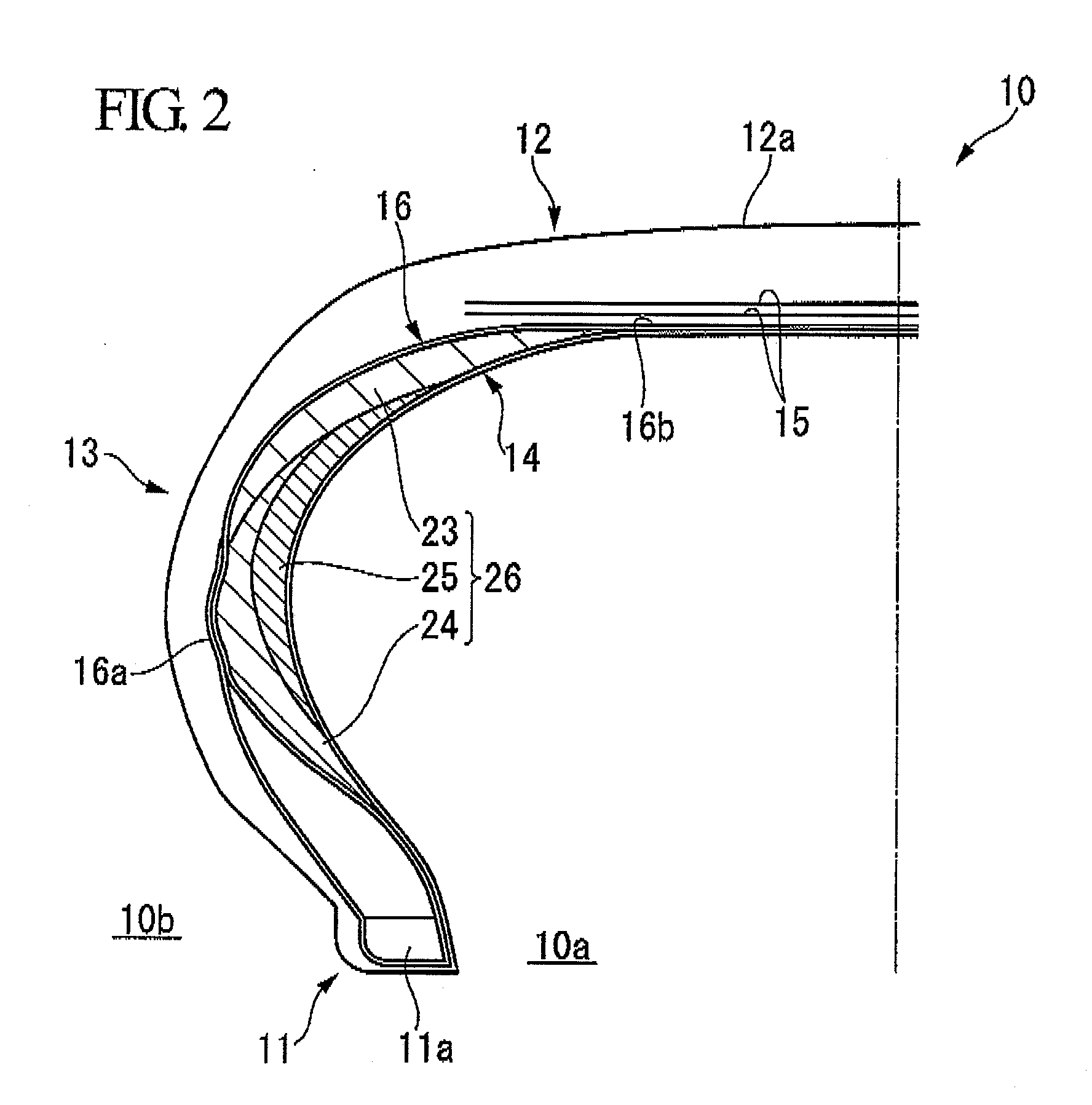
[0038]Hereinafter, one embodiment of a pneumatic tire related to this invention will be described, referring to FIG. 1. FIG. 1 shows a portion of a cross-sectional view of a pneumatic tire 10. This pneumatic tire includes a pair of right and left bead parts 11, a tread part 12 arranged outside the bead parts 11 in the radial direction of a tire, and having a tread 12a of the tire, and a pair of right and left sidewall parts 13 connecting both ends of the tread part 12 in the width direction and the bead parts 11. In addition, an inner peripheral surface of the pneumatic tire 10 is constituted by an inner liner 14.

[0039]A carcass layer 16 which extends in a toroidal shape between bead cores 11 a buried in the pair of right and left bead parts 11, respectively, are provided inside the bead parts 11, the sidewall parts 13, and the tread part 12 over these respective parts.

[0040]Both ends of the carcass layer 16 in the width direction of the tire constitutes folded ends 16a turned back ...


PUM

PropertyMeasurementUnit
pressureaaaaaaaaaa
widthaaaaaaaaaa
internal pressureaaaaaaaaaa

Abstract

Reinforcing rubber which constitutes a reinforcing rubber layer in a pneumatic tire 10 is formed by winding a plurality of beltlike reinforcing rubber sheets adapted to have almost the same cross-sectional area and cross-sectional shape around a forming drum over its entire periphery while being shifted in the axial direction of the forming drum such that at least portions thereof in the width direction of the tire overlap each other over the whole periphery of the forming drum and by separately jointing both longitudinal ends of the respective reinforcing rubber sheets. As a result, a pneumatic tire with improved run-flat durability without hindering comfortable riding can be formed while hindrances to manufacture are minimized.

Description

TECHNICAL FIELD[0001]The present invention relates to a manufacturing method of a pneumatic tire to be used as a run-flat tire which can travel a predetermined distance even at the time of an abnormal drop in tire internal pressure, or blowout, and the pneumatic tire.[0002]Priority is claimed on Japanese Patent Application No. 2006-119132, filed Apr. 24, 2006, the content of which is incorporated herein by reference.BACKGROUND ART[0003]This type of pneumatic tire includes a pair of right and left bead parts, a tread part arranged outside the bead parts in the radial direction of a tire, and having a tread of the tire, and a pair of right and left sidewall parts connecting both ends of the tread part in the width direction and the bead parts, as disclosed in the following Patent Documents 1 and 2. In this type of tire, a carcass layer which extends in a toroidal shape between bead cores buried in the pair of right and left bead parts, respectively, are provided inside the bead parts,...

Claims


Application Information

Patent Timeline
Patent Type & Authority Applications(United States)
IPC IPC(8): B29D30/08
CPCB29D30/3007B29D30/72B29D2030/201B60C17/0027B60C17/00B60C2001/0033B29D2030/724
Inventor KOBAYASHI, TOSHINOBU
Owner BRIDGESTONE CORP
Learn More